


 English
 Français
 русский
 عربى
عربى Español
 Deutsch
Tel
+86 186 2508 0683

Modern automation systems increasingly require linear motion that is fast, accurate, rigid, and dependable over long travel distances. In applications such as high-speed scanning, material transfer, inspection, dispensing, packaging, semiconductor handling, and large-format equipment, the motion module is often one of the most important determinants of overall machine performance. A linear axis must move smoothly, control position precisely, resist mechanical deflection, and maintain consistent performance throughout its service life.
The TYSM14-S is a large linear motor module developed for these requirements. It combines a 145 mm-wide body, an integrated four-guide-rail structure, and a light-duty carriage to create a long-travel axis for light-to-medium load automation. The module provides a maximum stroke of 3,720 mm, a maximum speed of 2,000 mm/s, maximum acceleration of 2 G, and continuous thrust of 225 N. Under specified operating conditions, it can handle a maximum load of 60 kg.
Unlike a conventional screw-driven actuator, the TYSM14-S uses direct linear motor drive technology. This eliminates the need for a rotating screw, nut, belt, or similar mechanical transmission element between the motor and the moving carriage. The result is a clean and responsive motion system with fewer wear-prone transmission components, high acceleration capability, and strong suitability for repeated rapid positioning.
The module is manufactured by Suzhou Tongyousheng Electronic Technology Co., Ltd., a Chinese high-tech enterprise specializing in electric cylinders, linear motion modules, linear motor modules, servo presses, robotic seventh axes, and multi-degree-of-freedom motion platforms. Its experience in automation equipment, precision machining, control technology, and integrated motion systems supports the development of linear modules intended for demanding industrial environments.
This article examines the design, operating characteristics, advantages, engineering considerations, manufacturing strengths, and application value of the TYSM14-S. It also explains how the four-guide structure and light-carriage design help the module compete with other long-travel linear motion solutions.
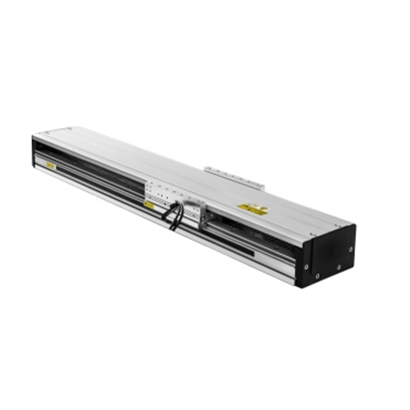
High-Precision 4-Guide Light-Carriage Large Linear Motor
The TYSM14-S is classified as a large linear motor module. It is designed around an integrated guide-and-drive architecture in which the motor, guide system, structural body, and carriage form a coordinated linear motion assembly. The module is intended to reduce the engineering work required when building a long-travel automation axis, while providing a stable foundation for payload mounting and precision movement.
Its 145 mm body width provides a practical balance between structural capacity and installation efficiency. A wider body generally allows more room for guide spacing, structural reinforcement, cable routing, and mounting interfaces. In the TYSM14-S, the body supports four guide rails rather than relying on a basic two-rail arrangement. This creates a broader and more stable support geometry for the carriage.
The module can be configured for different lengths. The available structural data lists module lengths from 340 mm to 3,996 mm, with different combinations of K, N, L, and module weight values. The maximum stated stroke is 3,720 mm. This range allows machine designers to select a module size that corresponds closely to the required travel rather than adapting a machine around a fixed short-stroke actuator.
The light-carriage design is particularly important. Reducing moving mass allows the motor to devote more of its available force to useful acceleration, payload movement, and dynamic response. A lighter carriage can also reduce the energy required for repeated reciprocating movement. In high-cycle equipment, this can contribute to improved throughput and lower mechanical stress on the entire machine.
The TYSM14-S is suitable for applications where the payload is significant but not extreme, and where long travel, high speed, and responsiveness are more important than very high continuous thrust. It is therefore positioned between compact precision stages and heavy-duty linear transport systems.
| Parameter | Specification |
|---|---|
| Product model | TYSM14-S |
| Product type | Large linear motor module |
| Body width | 145 mm |
| Maximum speed | 2,000 mm/s |
| Continuous thrust | 225 N |
| Maximum stroke | 3,720 mm |
| Maximum acceleration | 2 G |
| Maximum load | 60 kg at 0.5 m/s and 0.5 G operating conditions |
| Guide structure | Integrated four-rail guide system |
| Service life | Guaranteed 10,000 km under normal use and catalog-compliant conditions |
| Static loading moments | MY: 3,483 N·m; MP: 3,483 N·m; MR: 5,120 N·m |
The specifications should be interpreted together rather than individually. Maximum speed, acceleration, payload, orientation, duty cycle, external moments, and installation conditions all influence the actual operating envelope. A system operating with a high payload or high acceleration may not be able to use the maximum speed simultaneously. Proper sizing should therefore be completed using the complete load, inertia, speed, acceleration, and installation data.
A direct linear motor converts electrical energy into straight-line force without first producing rotary motion. In a screw-driven actuator, the motor rotates a screw and the nut translates along the screw. In a belt-driven axis, the motor rotates a pulley and the belt transfers force to the carriage. A direct linear motor instead produces electromagnetic force directly along the travel direction.
This operating principle offers several important advantages. First, it reduces the number of mechanical transmission components. There is no screw thread, nut assembly, belt, pulley, or gearbox required to transfer motor rotation into carriage movement. Fewer transmission elements can mean less backlash, less mechanical compliance, and fewer components subject to wear.
Second, direct drive supports rapid changes in velocity. The carriage can accelerate and decelerate without waiting for a screw or belt transmission to respond. This is valuable in scanning applications, pick-and-place equipment, inspection machinery, and other systems with repeated short moves or high-frequency reversals.
Third, direct drive avoids the speed limitations associated with long rotating screws. As screw length increases, critical-speed concerns, vibration, whip, and rotational inertia can make very high speeds difficult to achieve. A linear motor is not subject to screw whip in the same way. This makes it especially suitable for a stroke of several meters, where a conventional screw axis may become mechanically complicated or require additional support.
Compared with belt-driven systems, a direct linear motor can offer improved positioning consistency because the motion does not depend on belt tension, belt elasticity, or pulley engagement. Belts remain useful and economical for many applications, but their performance can be affected by stretch, tension variation, aging, and dynamic vibration. The TYSM14-S is designed for users who require a more direct and rigid motion architecture.
Direct-drive technology also supports clean machine design. Because there is no lubricated screw and nut pair, maintenance requirements may be reduced in suitable environments. Nevertheless, the guide rails and bearings still require appropriate cleanliness, lubrication, inspection, and environmental protection. Direct drive does not eliminate all maintenance; it changes the maintenance profile of the axis.
The TYSM14-S can reach a maximum speed of 2,000 mm/s and a maximum acceleration of 2 G. These figures make it appropriate for high-throughput automation in which the axis must complete long movements rapidly. The light carriage supports this dynamic performance by minimizing the mass that the motor must repeatedly accelerate.
High acceleration is also useful when the required travel is moderate but cycle time is short. A machine may need to move from one station to another, perform a process, return, and repeat thousands of times per day. In such a system, acceleration and deceleration often influence productivity more than the absolute top speed. The motor module is therefore valuable not only for long moves but also for fast indexing and frequent repositioning.
To use this capability correctly, the motion controller, servo amplifier, feedback device, and mechanical payload must be selected as a coordinated system. Acceleration profiles should account for payload inertia, center-of-gravity offset, guide loading, and the need to avoid vibration at the end of a move. Proper tuning is essential for taking full advantage of the module’s dynamic potential.
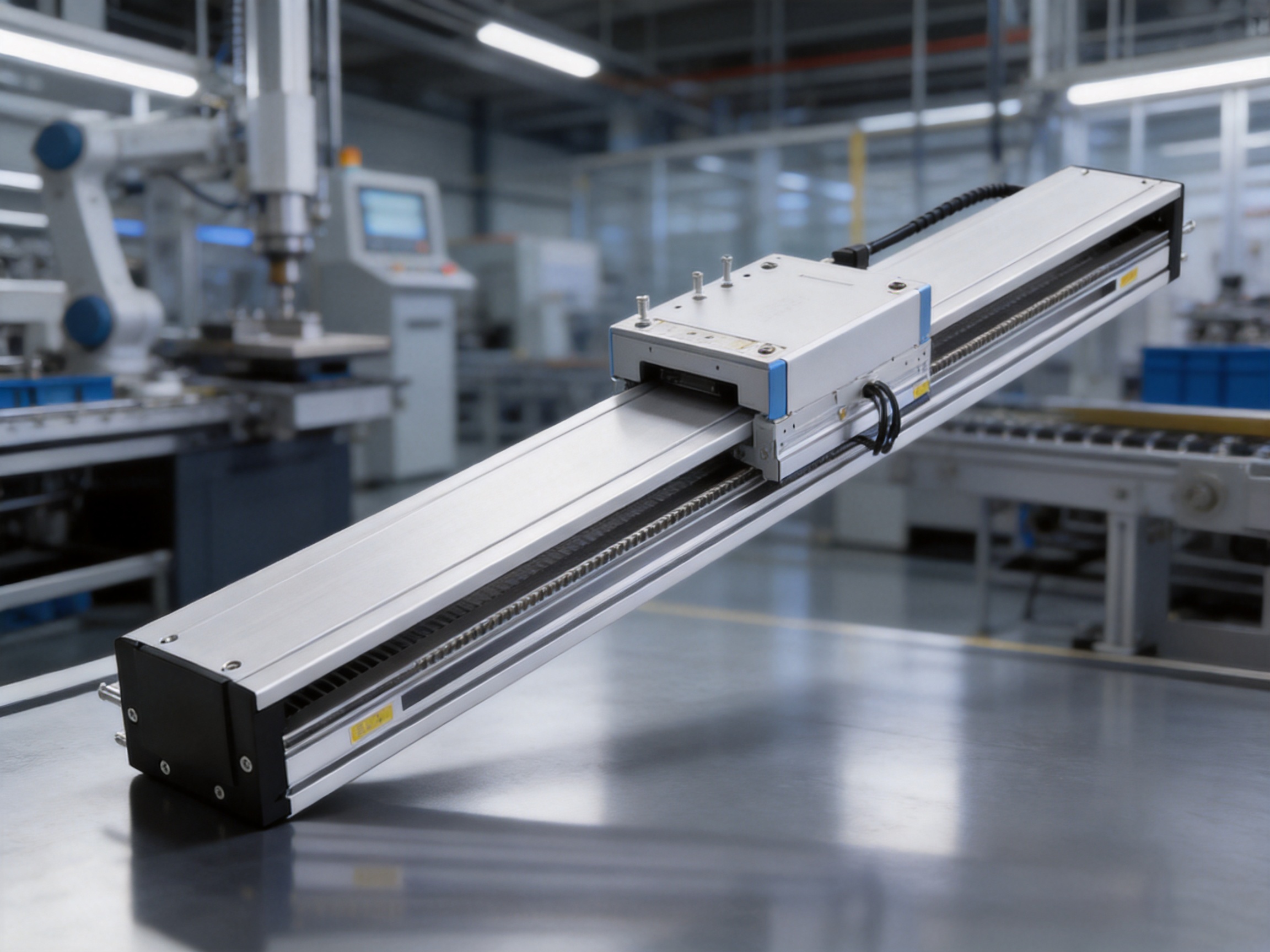
The integrated four-rail guide system is one of the most distinctive features of the TYSM14-S. Guide rails are responsible for constraining the carriage, supporting external loads, and resisting moments generated when the center of gravity is offset from the guide plane. A four-rail configuration distributes these forces across multiple guiding elements and provides a stable platform for mounted tooling.
In a two-rail system, the guide arrangement may be adequate for centered loads and moderate moments. However, large-format equipment often includes tooling, sensors, grippers, vacuum heads, or workpieces that extend away from the axis centerline. This produces pitch, yaw, or roll moments. A four-rail system can provide improved resistance to these loads when properly designed and installed.
The broad support geometry also helps reduce carriage twisting. When the carriage is subjected to an uneven load, a wider and more distributed guide arrangement can maintain better contact across the carriage. This is useful in applications where the workpiece is loaded on one side, where the tool changes position, or where the carriage must maintain orientation during acceleration.
The listed static loading moments are MY 3,483 N·m, MP 3,483 N·m, and MR 5,120 N·m. These values indicate the module’s stated static moment capacity in the relevant axes. Engineers should compare the actual payload center of gravity, offset distance, acceleration, and external process forces with these values. Dynamic loading should not be assessed using static values alone.
Rigidity is especially important in precision scanning and inspection. Any deflection between the tool and the workpiece can appear as measurement error, image distortion, or inconsistent processing. A stable guide structure helps maintain the relationship between the carriage-mounted equipment and the fixed machine frame.
The four-guide design also contributes to smooth running. When the carriage is adequately supported and the guide rails are accurately aligned, the system can move with low friction and reduced tendency toward binding. This is particularly important for long modules, where small alignment errors can accumulate over the travel length.
Many real-world payloads are not perfectly centered. A camera may be mounted above the carriage, a gripper may extend forward, or a processing head may be positioned to one side. The resulting moment increases as the offset from the guide plane increases. The guide system must resist this moment without excessive deflection or uneven bearing loading.
The four-rail arrangement provides more contact points and a larger effective support area than a simple guide configuration. This can improve stability under off-center loading, provided that the payload remains within the specified load and moment limits. It also gives machine designers greater flexibility when creating mounting plates and tool interfaces.
For long-travel equipment, the guide structure must work together with the machine frame. A high-capacity carriage cannot compensate for a weak or poorly aligned support structure. The mounting surface should be sufficiently flat, rigid, and continuous, and installation should follow the manufacturer’s recommended procedures.
The carriage is the moving part of the module and serves as the interface between the linear motor and the customer’s tooling. The TYSM14-S uses a light-duty carriage concept that prioritizes low moving mass and high responsiveness. This is a useful design choice for systems that do not require the extreme payload capacity of a heavy industrial slide.
Every kilogram added to the moving assembly increases the force required for acceleration. At 2 G, even a moderate increase in mass creates a substantial increase in required dynamic force. A lighter carriage leaves more of the available thrust for payload movement and process control. It can also reduce settling time after a rapid move, although final settling performance depends on the complete machine structure and servo tuning.
Low moving mass may improve energy efficiency during repeated reciprocating cycles. The energy required to accelerate and decelerate the carriage is related to its mass and velocity. Reducing unnecessary moving mass can therefore be beneficial in high-cycle equipment, especially when the axis performs continuous back-and-forth motion.
The light-carriage approach also supports compact tooling. Designers can mount inspection cameras, laser heads, transfer grippers, dispensing nozzles, small machining tools, or other process devices without immediately consuming the entire dynamic capacity of the axis.
However, light carriage does not mean unlimited payload flexibility. The maximum load depends on speed, acceleration, orientation, center of gravity, external forces, and moment loading. A payload that is acceptable in a horizontal installation at low acceleration may not be acceptable in a wall-mounted configuration or at 2 G acceleration.
The principal maximum-load specification is 60 kg under 0.5 m/s and 0.5 G operating conditions. The load tables also provide guidance for different horizontal and wall-mounted configurations at several combinations of speed and acceleration.
| Installation and operating condition | Representative payload values listed | Engineering significance |
|---|---|---|
| Horizontal installation, 0.5 m/s and 5 m/s² | 40 kg, 50 kg, and 60 kg entries | Suitable for heavier loads at moderate dynamic demand |
| Wall-mounted installation, 0.5 m/s and 5 m/s² | 25 kg, 30 kg, and 38 kg entries | Orientation affects guide loading and allowable payload |
| Horizontal installation, 0.8 m/s and 8 m/s² | 30 kg, 40 kg, and 50 kg entries | Higher acceleration reduces allowable payload |
| Horizontal installation, 1 m/s and 10 m/s² | 25 kg, 28 kg, and 35 kg entries | Useful for faster indexing with moderate loads |
| Horizontal installation, 1.5 m/s and 15 m/s² | 8 kg, 13 kg, and 18 kg entries | High acceleration is intended for lighter payloads |
| Horizontal installation, 2 m/s and 20 m/s² | 7 kg, 9 kg, and 11 kg entries | Maximum-speed operation requires careful payload control |
The values in the table demonstrate an important design principle: payload capacity and dynamic performance must be balanced. At lower speeds and accelerations, the module can support greater loads. At higher acceleration, the same load creates greater inertial forces and moments. The load tables should be used during preliminary design, followed by a detailed application review.
A maximum stroke of 3,720 mm gives the TYSM14-S a substantial operating range for a single linear axis. Long travel is valuable in production lines that need to connect multiple process stations, move across large work areas, or scan large workpieces without using several short axes.
One long axis can simplify machine architecture. Instead of installing multiple actuators with transfer mechanisms between them, a machine builder may use one continuous module and position the carriage at different stations. This can reduce the number of mechanical interfaces, transfer operations, and potential sources of alignment error.
Long stroke is also useful in large-format inspection. A camera or sensor can travel across a workpiece, panel, web, or assembly while maintaining a consistent reference structure. In material handling, the same capability allows a gripper or vacuum tool to serve several loading and unloading locations.
Long-travel linear motors avoid some of the limitations found in long screw systems. A several-meter screw may require intermediate supports, careful balancing, and management of rotational vibration. A belt axis may require tension adjustment and may be affected by elastic behavior. A rack-and-pinion axis can provide long travel but may introduce backlash or require complex precision calibration. Direct linear motor architecture offers an alternative for applications that prioritize responsiveness and precision.
The module-length data provides multiple standard configurations. Listed lengths range from 340 mm to 3,996 mm, with module weights increasing as the body becomes longer. This standardized approach can help reduce custom engineering and make replacement planning easier.
| Example module length | Listed module weight | Potential design use |
|---|---|---|
| 340 mm | 11 kg | Compact long-axis or limited travel installation |
| 1,000 mm | 19.8 kg | Medium-range positioning and transfer |
| 1,600 mm | 27.8 kg | Extended process-area coverage |
| 2,496 mm | 39.8 kg | Large equipment and multi-station transfer |
| 3,396 mm | 51.8 kg | Large-format scanning and material movement |
| 3,996 mm | 59.8 kg | Near-maximum standard module length |
The listed lengths and weights are configuration references. The final selection must also consider the required effective stroke, end clearances, cable routing, sensors, mounting supports, carriage dimensions, and installation access.
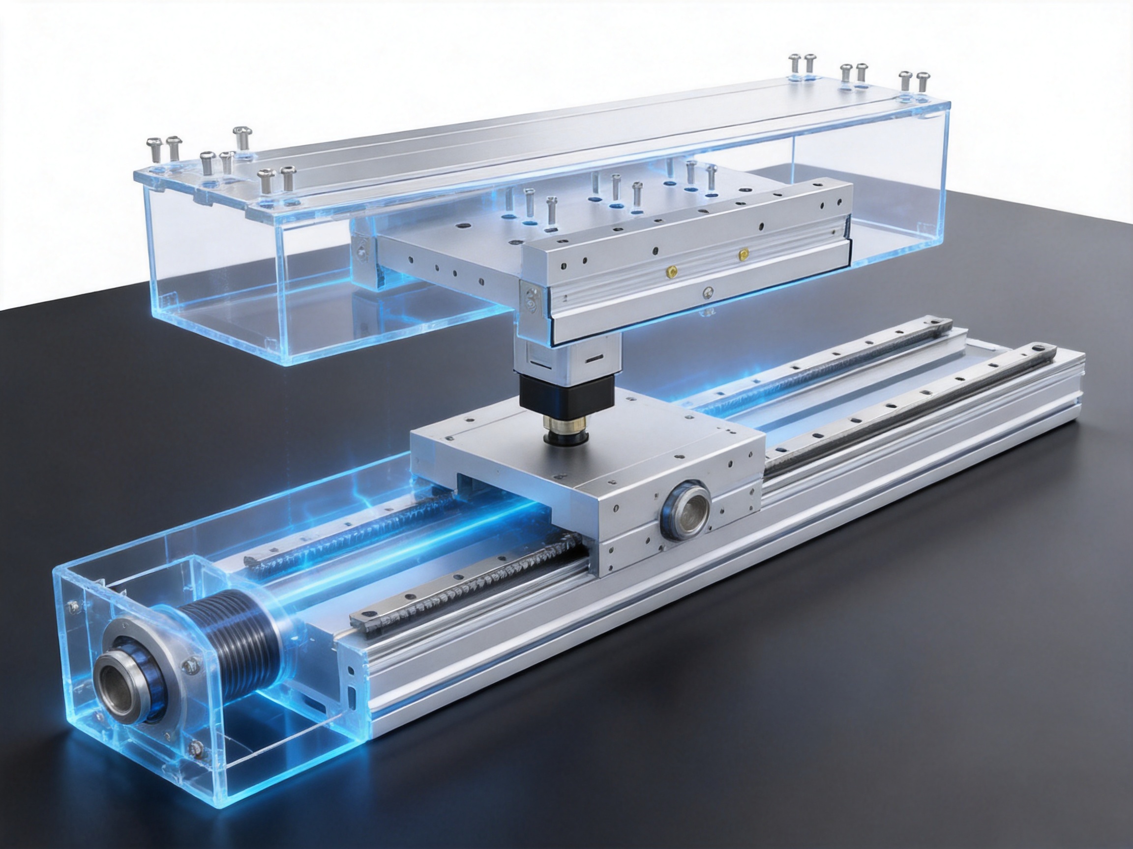
The TYSM14-S competes with several types of linear motion products, including ball-screw modules, belt-driven actuators, rack-and-pinion systems, and other direct-drive linear motor stages. Each technology has a valid application range, but the TYSM14-S offers a strong combination of long travel, high speed, four-rail support, and light moving mass.
Ball-screw actuators are widely used because they can deliver high thrust and good positioning accuracy. They are often effective for short and medium travel. However, as stroke increases, screw rotation introduces critical-speed limitations and mechanical vibration concerns. Long screws may require support bearings or special structural arrangements.
The TYSM14-S avoids screw whip and rotating-screw inertia because the drive force is generated directly along the axis. This allows the module to achieve a maximum speed of 2,000 mm/s over a long travel range. The direct-drive arrangement also reduces backlash-related concerns associated with screw-and-nut transmission, although overall positioning accuracy still depends on feedback, control, thermal conditions, structure, and installation quality.
A ball screw may remain preferable when extremely high thrust, self-locking behavior, or low initial cost is the primary requirement. The TYSM14-S is more attractive when high speed, rapid reversals, long stroke, and reduced transmission complexity are central to the application.
Belt-driven actuators are popular for their long travel, relatively low weight, and economical construction. They can provide high speed, but belt elasticity, tension variation, wear, and vibration may affect repeatability and dynamic stiffness. These factors become more important when the carriage carries an extended tool or when the system must perform precise scanning.
The TYSM14-S provides direct electromagnetic drive and a four-rail guide arrangement. This combination can offer a more rigid and responsive axis than a basic belt design. It is well suited to applications where the carriage must reverse rapidly, maintain tool orientation, or follow precise motion profiles.
A belt axis can still be the better choice for simple transport where accuracy requirements are moderate and cost sensitivity is high. The linear motor module is positioned for users who need enhanced dynamic behavior and a more integrated precision platform.
Rack-and-pinion systems are useful for very long travel and heavy loads. They can transmit considerable force, but gear engagement introduces backlash, tooth error, lubrication needs, and mechanical noise. Precision performance may require preload, compensation, or sophisticated calibration.
The direct-drive design of the TYSM14-S eliminates gear mesh along the motion path. It can therefore provide smooth force generation and quiet operation when properly controlled. The four-guide system further supports stability under carriage loading. For long but not extreme travel where precision and speed are more important than very high thrust, the module can be a compelling alternative.
Not all linear motor modules have the same guide architecture or carriage design. Some products use two guide rails, narrow bodies, or heavy carriages. The TYSM14-S differentiates itself through the combination of four integrated rails, a 145 mm body width, light-duty moving mass, 225 N continuous thrust, and a stroke approaching four meters in standard configurations.
This combination helps machine builders avoid choosing between a narrow precision stage and a large but slow transport axis. The TYSM14-S is designed as a balanced solution for applications that need a wide support platform and long travel without requiring a massive heavy-duty structure.
Scanning equipment requires controlled motion across a defined field while maintaining consistent speed and position. The TYSM14-S can move a camera, sensor, laser, or inspection head across a large work area. Its direct drive supports smooth velocity control, while the four-rail guide structure helps maintain tool stability.
In visual inspection, the carriage may carry a line-scan camera or lighting assembly. In dimensional inspection, it may carry a laser displacement sensor or measuring probe. In surface processing, it may carry a marking, cleaning, or treatment head. The long stroke reduces the need to reposition the workpiece or divide a large inspection area into several smaller zones.
Production lines often require a carriage to move parts between loading, processing, testing, and unloading stations. A long linear motor module can serve as a transfer axis across several stations. High acceleration can shorten the time spent traveling between locations, improving the cycle rate of the complete line.
The four-rail system is beneficial when the transferred object is held at an offset from the carriage. Grippers, vacuum tools, and product fixtures can create moments, especially during acceleration and deceleration. The guide structure provides a stable foundation for such tooling when the load remains within the rated limits.
Large-format equipment may include panel handling machines, large workpiece inspection systems, production equipment for sheet materials, and automated processing stations. These machines often require long travel without sacrificing repeatability. The TYSM14-S can be integrated into a rigid machine frame to create a large working envelope.
Its modular length options support equipment designers in selecting a body that closely matches the machine layout. This can reduce unused travel and help control overall equipment dimensions.
A robot mounted on a linear axis can travel along a production line, reach multiple workstations, or extend the robot’s working envelope. The TYSM14-S may be used as a seventh-axis platform for a robot or as a long base axis for a moving tool system, provided that the robot mass, center of gravity, acceleration profile, and overturning moments are evaluated carefully.
The four-guide configuration is useful for supporting an elevated or offset robotic payload. However, robot applications may impose significant dynamic moments, and the complete system must be reviewed rather than relying solely on the nominal payload value.
Electronic manufacturing applications often require low-vibration movement, accurate positioning, and repeatable scanning. A direct linear motor can support precise motion profiles without the mechanical backlash of conventional transmission systems. Cleanliness, environmental control, cable management, and suitable feedback integration are essential for these applications.
Dispensing heads, marking tools, adhesive applicators, and other process devices may need to move across large components. The module’s high speed and controllable motion can support rapid positioning between process points. The four-guide structure helps maintain the tool’s orientation and working distance, while the light carriage supports fast movement with small and medium tooling.
The performance of a linear motor module depends not only on its design concept but also on manufacturing accuracy. Guide alignment, structural straightness, mounting surfaces, motor components, carriage geometry, and assembly tolerances all influence the final result. Suzhou Tongyousheng Electronic Technology Co., Ltd. emphasizes integrated research and development, production, and sales, allowing product design and manufacturing knowledge to be coordinated within one organization.
The company maintains an experienced R&D team and uses advanced design software during product development. Engineering software supports structural analysis, component optimization, motor and guide layout, mounting-interface development, and evaluation of different module lengths. A design-led development process helps engineers balance speed, thrust, rigidity, payload, weight, and manufacturability.
High-precision CNC machining centers are used to produce structural components and mounting features. CNC processing supports consistent dimensions, repeatable hole patterns, accurate rail seats, and controlled surface geometry. These qualities are especially important for long linear modules, because small geometric errors can influence friction, carriage smoothness, and alignment over the entire travel range.
The company also reports a portfolio of core patents and ongoing investment in product development. Its product range includes electric cylinders, linear modules, linear motors, servo presses, motion platforms, and related control technologies. This broader product portfolio gives the engineering team exposure to multiple motion-control requirements rather than limiting development to a single actuator category.
Developing linear motion products alongside servo presses and multi-degree-of-freedom platforms encourages a system-level understanding of force, position, synchronization, and structural behavior. The same customer may require several types of motion equipment in one production line. A supplier that understands both linear axes and complete motion systems can provide more coordinated technical support.
The company collaborates with state-owned enterprises, defense technology institutions, and universities. These collaborations support the exchange of engineering knowledge and contribute to the development of motion simulation, linkage control, algorithmic software, and precision automation technologies.
Its development history includes linear modules, electric cylinders, servo presses, six-degree-of-freedom platforms, control software, and multi-degree-of-freedom platform linkage systems. This history indicates a focus on industrial motion technology rather than on isolated mechanical components alone.
For a long linear module, production consistency is essential. The guide rails must remain correctly aligned, the motor elements must be positioned accurately, and the carriage must travel without excessive resistance. Quality control should cover incoming materials, machining, dimensional inspection, assembly, electrical testing, motion testing, and final packaging.
The TYSM14-S is specified with a guaranteed service life of 10,000 km when used normally and in compliance with catalog conditions. This service-life statement provides an important reference for production planning and maintenance scheduling. Actual service life depends on contamination, lubrication, loading, installation, acceleration, operating frequency, and environmental conditions.
A professional supplier should also assist customers with application sizing, installation orientation, servo selection, feedback configuration, cable routing, and maintenance planning. These services can be as important as the hardware itself, particularly for long-travel precision systems.
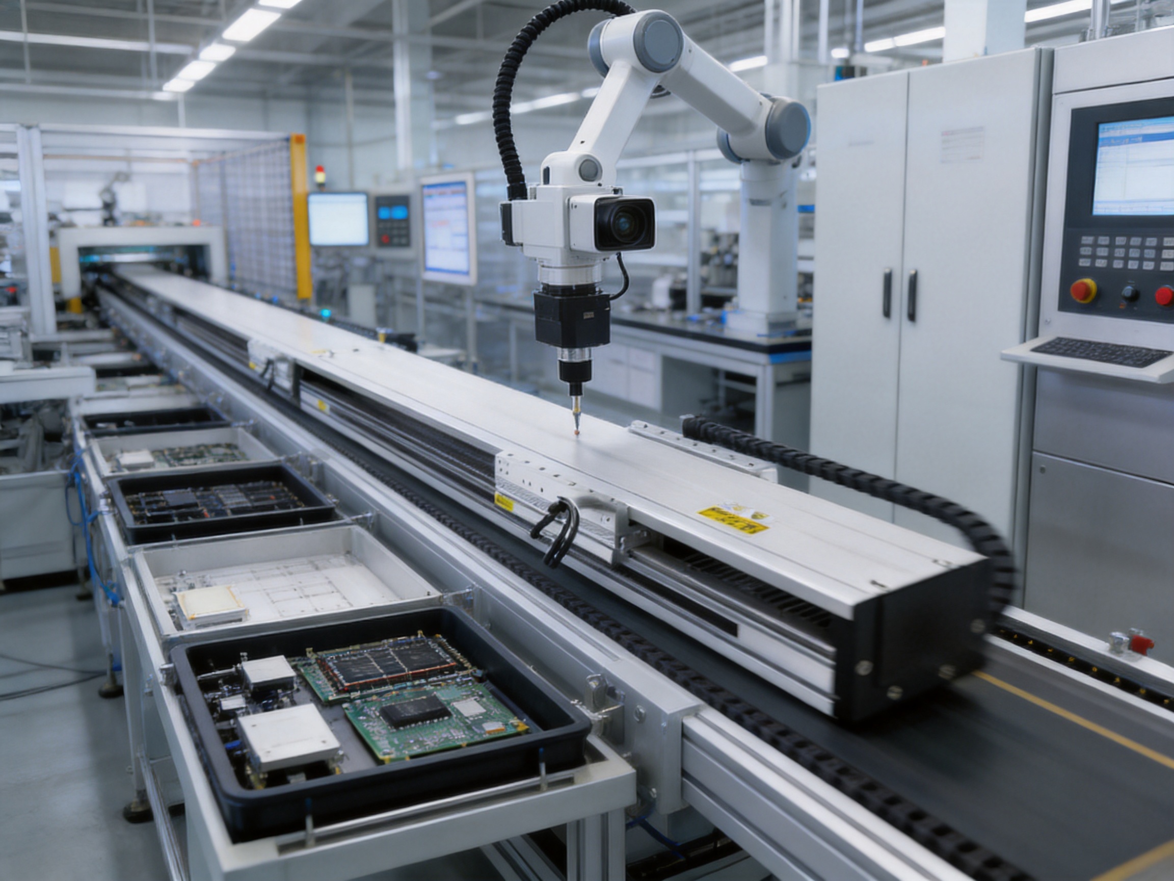
Correct installation is necessary to achieve the performance expected from the TYSM14-S. The mounting frame should have adequate rigidity and a suitable flatness level. If the base is uneven, the module may be forced into a distorted condition, increasing guide friction and reducing motion smoothness.
Long modules require special attention to support points and structural deflection. The support arrangement should follow the manufacturer’s recommended design. A support frame that is too flexible may cause vibration during acceleration, while excessive local distortion may affect guide alignment.
The module should be installed with sufficient clearance for the carriage, payload, cable carrier, sensors, and end-of-travel components. The effective application stroke should not be confused with the physical body length. End margins, deceleration zones, mechanical stops, and safety clearances must be included in the machine layout.
Horizontal installation generally provides the most favorable payload condition. The main load is supported by the guide system, while the motor supplies the force required for acceleration, deceleration, and friction compensation. The load table includes payload values for horizontal operation at different speeds and acceleration levels.
Even in horizontal use, the payload center of gravity should be measured from the guide plane. A high center of gravity can create pitch or roll moments during acceleration. The mounting plate should be designed to distribute the load across the carriage rather than concentrating force at a small area.
Wall-mounted installation changes the direction of gravity relative to the guide system. As a result, the allowable payload values are generally lower than those for comparable horizontal operating conditions. The data includes separate wall-mounted values, such as 25 kg, 30 kg, and 38 kg entries at 0.5 m/s and 5 m/s², depending on the relevant configuration.
Wall-mounted applications should be checked for carriage sag, bearing load distribution, cable-chain influence, emergency-stop behavior, and payload retention. Tooling should be secured so that gravity does not cause movement or part loss when the axis is disabled.
The standard specifications do not apply to ceiling-mounted inverted use. Customers requiring this orientation should contact the sales or engineering team for review. Inverted installation can change lubrication behavior, bearing loading, cable management, safety requirements, and the effects of gravity on the payload and carriage.
A linear motor module reaches its full potential when combined with a suitable servo drive and feedback system. The motor generates force, but the controller determines how that force is applied. The feedback device provides position information, enabling the servo system to correct errors and follow the programmed motion profile.
For high-speed scanning, the control system must maintain a stable velocity. For point-to-point transfer, it must provide rapid acceleration, controlled deceleration, and minimal settling time. For precision processing, it may need synchronized motion with a second axis, a camera trigger, a dispensing signal, or a robot controller.
Servo tuning should be completed after the module is installed with the actual payload and tooling. The mechanical resonance of the machine frame, carriage, payload plate, and mounted device can affect the appropriate control gains. Excessive gain may create vibration, while insufficient gain may lead to slow settling or tracking error.
Acceleration and jerk should also be considered. Although the module can reach 2 G maximum acceleration, a lower acceleration or smoother jerk-limited profile may be better for fragile products, liquid dispensing, optical inspection, or payloads with a high center of gravity. The best motion profile is determined by the process, not simply by the maximum rating.
The TYSM14-S can serve as one axis within a coordinated system. It may operate together with electric cylinders, servo presses, rotary stages, robotic arms, or other linear modules. In such systems, timing accuracy and communication performance are important.
A machine builder should define the required synchronization tolerance, trigger response, positioning repeatability, and emergency-stop behavior. The supplier’s experience in motion-control software and multi-degree-of-freedom platform linkage systems can be valuable when designing coordinated automation.
The guaranteed service life is 10,000 km under normal use and catalog-compliant conditions. This is a useful benchmark for evaluating the module in relation to production cycles. For example, a machine with a 2 m average carriage movement per cycle and 5,000 cycles per day would accumulate approximately 10 km per day, before considering additional movement or operating variations. Actual maintenance planning should use the real duty cycle.
Guide rails should be kept clean and lubricated according to the recommended procedure. Dust, metal particles, liquid contamination, and process residue can increase rolling resistance and damage guide components. In demanding environments, protective covers, bellows, positive air pressure, or enclosure systems may be required.
The cable management system should be inspected regularly. A cable carrier that is improperly supported or overloaded can introduce additional force to the carriage. These forces may create vibration or interfere with smooth movement. Cables should have the correct bend radius and should be separated from sources of heat, sharp edges, and excessive abrasion.
Fasteners and payload mounting interfaces should be checked for loosening, especially during the initial operating period and after repeated high-acceleration cycles. Any change in noise, vibration, positioning behavior, or motor temperature should be investigated promptly.
Service life can be reduced by exceeding the rated load, operating at excessive acceleration, applying high external moments, installing the module on an unsuitable base, or using it in a contaminated environment. Good maintenance cannot compensate for incorrect sizing, so application review remains the first step in achieving reliable operation.
A linear motor module can move heavy equipment at high speed. The machine must therefore include appropriate guarding, emergency-stop functions, overtravel protection, collision detection where required, and safe access procedures. The module should not be treated as a complete safety system by itself.
Mechanical end stops and limit sensors should be selected according to the application. Software limits are useful but should not be the only protection against overtravel. The emergency-stop design should consider the stopping distance at maximum speed, the inertia of the payload, and the consequences of removing servo power.
During risk assessment, engineers should identify pinch points between the carriage and fixed structures, exposed moving tools, falling loads in vertical orientations, and unexpected movement after a power interruption. Wall-mounted and inverted applications require particular attention to payload retention and brake requirements.
The electrical installation should follow applicable industrial standards. Motor cables, feedback cables, grounding, shielding, and drive settings should be selected to reduce electromagnetic interference. Correct cable routing is especially important in long-travel applications because the cable path may be extended and repeatedly flexed.
Original equipment manufacturers need more than an actuator with attractive headline specifications. They need a product that can be integrated efficiently, configured for different machine sizes, supported during commissioning, and maintained over many years. The TYSM14-S offers several features that support this type of equipment development.
Its modular length range allows the same product family to be used in different machine platforms. Engineers can standardize interfaces, control strategies, spare parts, and maintenance procedures across equipment models. This reduces the number of unrelated motion products that must be qualified and supported.
The integrated four-rail guide system reduces the need for the OEM to design a separate guide structure around the motor. A separate guide system may require additional alignment, mounting, lubrication, and structural analysis. An integrated solution can shorten mechanical development time and simplify assembly, provided that the module is correctly matched to the payload.
The light carriage supports compact and dynamic tooling. Machine builders can design fast transfer or scanning equipment without using an oversized heavy-duty actuator. At the same time, the 145 mm body width provides a more substantial structural platform than many narrow linear axes.
Long travel makes the module suitable for large equipment and multi-station production lines. The OEM can use one axis to connect several process locations, reducing the need for intermediate transfer mechanisms. This may simplify programming and reduce synchronization issues between multiple short axes.
The manufacturer’s broader product portfolio also creates opportunities for integrated sourcing. A customer may combine the linear motor module with electric cylinders, servo presses, robotic axes, or motion platforms from the same technical partner. This can improve coordination of mechanical interfaces, control requirements, and after-sales support.
Automation equipment rarely operates under identical conditions. Stroke, payload, installation orientation, cable length, feedback requirements, carriage tooling, environmental protection, and controller compatibility may vary from one project to another. A technical discussion before ordering is therefore recommended.
Potential customization topics may include module length, carriage mounting arrangements, sensor positions, cable management, motor and drive matching, feedback selection, protective covers, and integration with the customer’s control architecture. The final options depend on the manufacturer’s standard product platform and engineering evaluation.
Customers should provide the following information during the selection process:
1. Required effective stroke and total available installation length.
2. Payload mass, including the carriage-mounted tooling, cables, fixtures, and workpiece.
3. Payload center of gravity and its offset from the carriage and guide plane.
4. Required speed, acceleration, jerk, cycle time, and movement frequency.
5. Installation orientation, including horizontal, wall-mounted, or special arrangements.
6. External forces, process forces, vibration sources, and collision risks.
7. Required positioning accuracy, repeatability, velocity stability, and synchronization performance.
8. Environmental conditions, including temperature, dust, moisture, oil mist, chemicals, and cleanroom requirements.
9. Servo drive, controller, network, feedback, and safety-system requirements.
10. Expected service life, annual operating hours, and maintenance resources.
Providing this information helps the supplier verify the application rather than selecting a product solely by nominal payload or stroke.
Suzhou Tongyousheng Electronic Technology Co., Ltd. was established in 2013. The company integrates research and development, production, and sales, with a focus on automation equipment and motion-control components. Its product categories include electric cylinders, linear motion modules, linear motor modules, servo presses, robotic seventh axes, and six-degree-of-freedom platforms.
The company describes quality, reputation, innovation, and development as its core values. Its mission is to support industrial progress through engineering innovation and craftsmanship while building long-term relationships with customers around the world.
Its manufacturing and engineering capabilities include an experienced R&D team, advanced design software, high-precision CNC machining centers, and core technology patents. These resources support the development of products that must combine mechanical accuracy, control performance, structural strength, and production repeatability.
The company’s cooperation with state-owned enterprises, defense technology institutions, and universities supports the exchange of technical knowledge. Such cooperation is relevant to applications involving simulation, robotics, precision automation, and intelligent manufacturing.
In addition to individual products, the company has developed algorithmic control software and multi-degree-of-freedom platform linkage systems. This experience is beneficial for customers seeking more than a standalone linear axis, particularly when multiple motion systems must operate as one coordinated machine.
The TYSM14-S is recommended when the application requires a long travel range, high speed, rapid response, and a stable carriage for light-to-medium loads. It is particularly suitable when the customer wants to avoid the limitations of long screws, the elasticity of belts, or the backlash of rack-and-pinion transmission.
It is a strong candidate for horizontal applications involving payloads up to the listed 60 kg condition, as well as for faster applications involving lighter payloads. The load tables should be consulted carefully because the allowable mass changes with acceleration, speed, orientation, and mounting configuration.
The module may not be the best choice when the primary requirement is extremely high thrust, very heavy payload movement, a self-locking vertical axis, or the lowest possible initial equipment cost. In those cases, a ball screw, rack-and-pinion system, or heavy-duty actuator may be more appropriate.
However, for precision transfer, long-format scanning, high-speed indexing, and dynamic automation, the balance of direct drive, four-rail guidance, long stroke, and light carriage provides a compelling technical proposition.
The TYSM14-S is a large linear motor module with an integrated four-guide-rail system and a light-duty carriage. It is designed for long-travel, high-speed, precision automation applications involving light-to-medium payloads.
The maximum stated stroke is 3,720 mm. The available configuration data lists module lengths from 340 mm to 3,996 mm, allowing the product to be adapted to different machine layouts.
The maximum speed is 2,000 mm/s. The usable speed in a specific machine depends on payload, acceleration, travel distance, servo tuning, safety margins, and environmental conditions.
The module provides 225 N of continuous thrust. Peak thrust and short-term dynamic performance should be confirmed with the manufacturer according to the selected motor, drive, duty cycle, and application requirements.
The listed maximum load is 60 kg under 0.5 m/s and 0.5 G operating conditions. Payload capacity changes according to speed, acceleration, installation orientation, center of gravity, and external moment loading.
Four guide rails distribute carriage loads over a broader support structure and improve resistance to pitch, yaw, and roll moments. This is useful for offset tooling, extended payloads, scanning heads, grippers, and large-format equipment.
The available data includes wall-mounted installation conditions. Wall-mounted payload values differ from horizontal values because gravity changes the guide loading. Ceiling-mounted inverted use is not covered by the standard specifications and requires technical confirmation.
It may be suitable for robotic seventh-axis applications when the robot mass, center of gravity, acceleration, moment loads, and safety requirements remain within the module’s capabilities. A complete application review is recommended before selection.
The guaranteed service life is 10,000 km when the product is used normally and in accordance with the catalog specifications. Contamination, excessive loading, poor alignment, high acceleration, and inadequate maintenance can reduce service life.
Typical applications include high-speed scanning, precision material transfer, large-format inspection, automated panel handling, robotic travel axes, dispensing, marking, electronic equipment, and other long-travel automation systems.
The linear motor provides direct force without a rotating screw. This makes it more suitable for long stroke and high speed, while reducing concerns associated with screw whip, backlash, and transmission inertia. Ball screws may remain preferable where very high thrust or low initial cost is more important.
Maintenance includes keeping the guide system clean, applying suitable lubrication, inspecting cable management, checking fasteners, monitoring vibration and noise, and verifying that the payload and operating conditions remain within specification.
The manufacturer’s product range and engineering background cover linear modules, electric cylinders, servo presses, robotic axes, motion platforms, and control software. Customers can discuss motor selection, feedback, mounting, cable routing, installation orientation, and coordinated motion requirements with the technical team.
The TYSM14-S is a high-precision large linear motor module designed for demanding long-travel automation. Its 145 mm body width, four integrated guide rails, light carriage, 225 N continuous thrust, 2,000 mm/s maximum speed, 2 G maximum acceleration, and 3,720 mm maximum stroke create a balanced solution for high-speed and precision motion.
Its strongest competitive advantages come from the combination of direct linear motor drive and broad four-rail guidance. Direct drive supports rapid acceleration, smooth response, and reduced transmission complexity. The four-guide structure provides improved rigidity and stability for off-center tooling and dynamic payloads. The light-carriage concept helps maintain responsiveness while supporting useful light-to-medium load capacity.
The module is well suited to scanning, material transfer, large-format automation, robotic seventh axes, inspection, dispensing, marking, and other applications where a conventional screw, belt, or rack solution may introduce unwanted limitations.
Its performance is supported by the manufacturer’s integrated R&D and production capabilities, high-precision CNC machining resources, design expertise, patent portfolio, and experience across a broad range of automation products. This combination gives OEMs and system integrators access to both a precision motion component and a potential long-term technical partner.
As with any precision actuator, successful implementation depends on correct sizing, a rigid mounting structure, appropriate servo control, suitable feedback, proper cable management, and regular maintenance. When these factors are addressed, the TYSM14-S can provide a reliable and efficient foundation for high-speed, long-distance industrial motion.
1. TYSM14-S Large Linear Motor Module Product Specifications, manufacturer-provided technical data.
2. Linear Motion Engineering Principles, including guide-load distribution, moment calculation, and actuator sizing practices.
3. Industrial Servo System Design Guidelines, covering feedback selection, acceleration profiles, tuning, and synchronization.
4. Precision Automation Equipment Maintenance Practices, including guide lubrication, contamination control, cable management, and service-life planning.
5. Manufacturer Company Profile and Product Development Information, Suzhou Tongyousheng Electronic Technology Co., Ltd.
6. General Application Engineering Reference for Linear Motors, Ball Screws, Belt Drives, and Rack-and-Pinion Motion Systems.
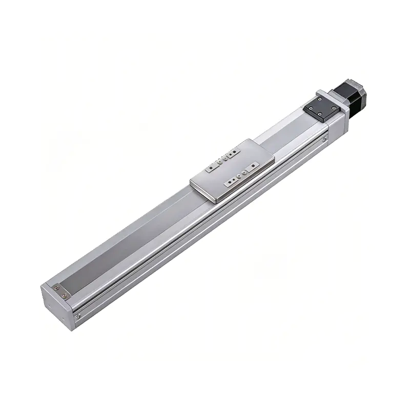 0.01mm High Precision Ball Screw Driven Rail-Embedded Linear Module
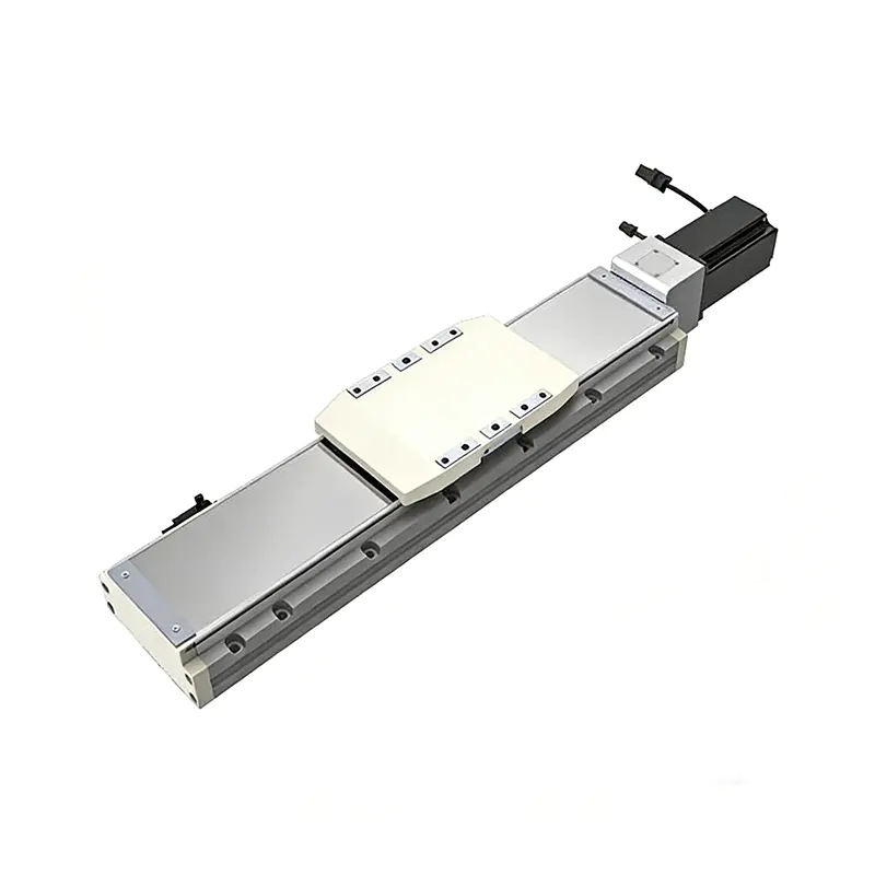 Heavy Load Ball Screw Driven Rail-Embedded Linear Module
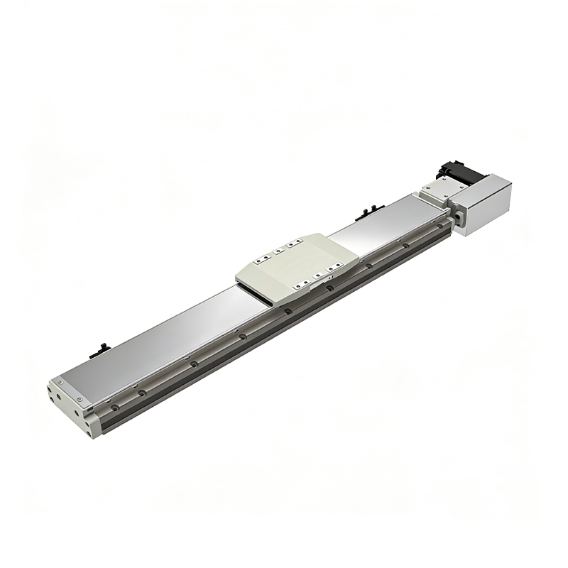 110KG Load Long Stroke Rail-Embedded Linear Module
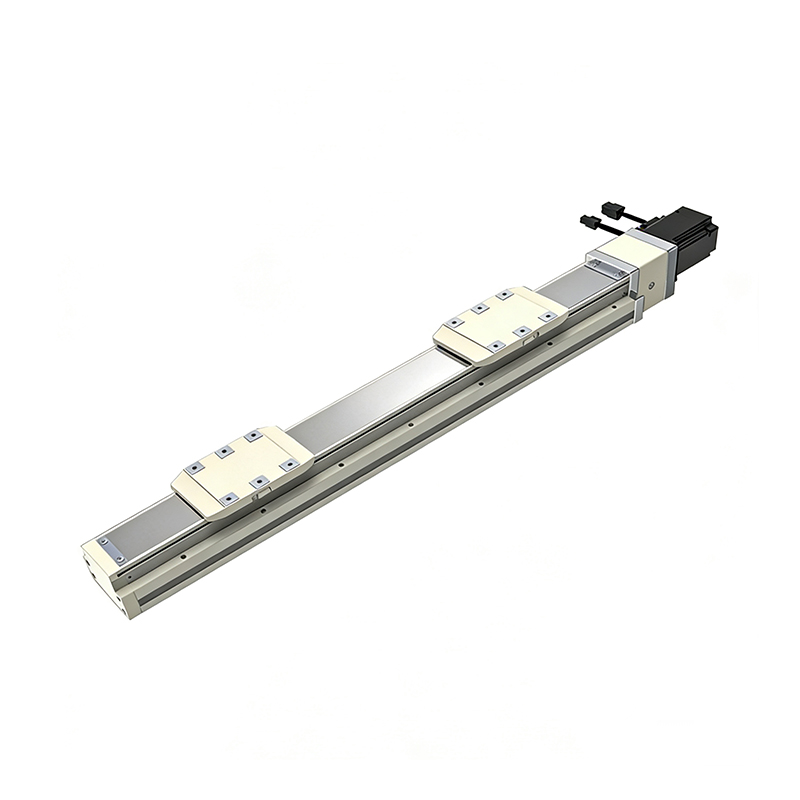 Dual-Slider High Precision Rail-Embedded Linear Module
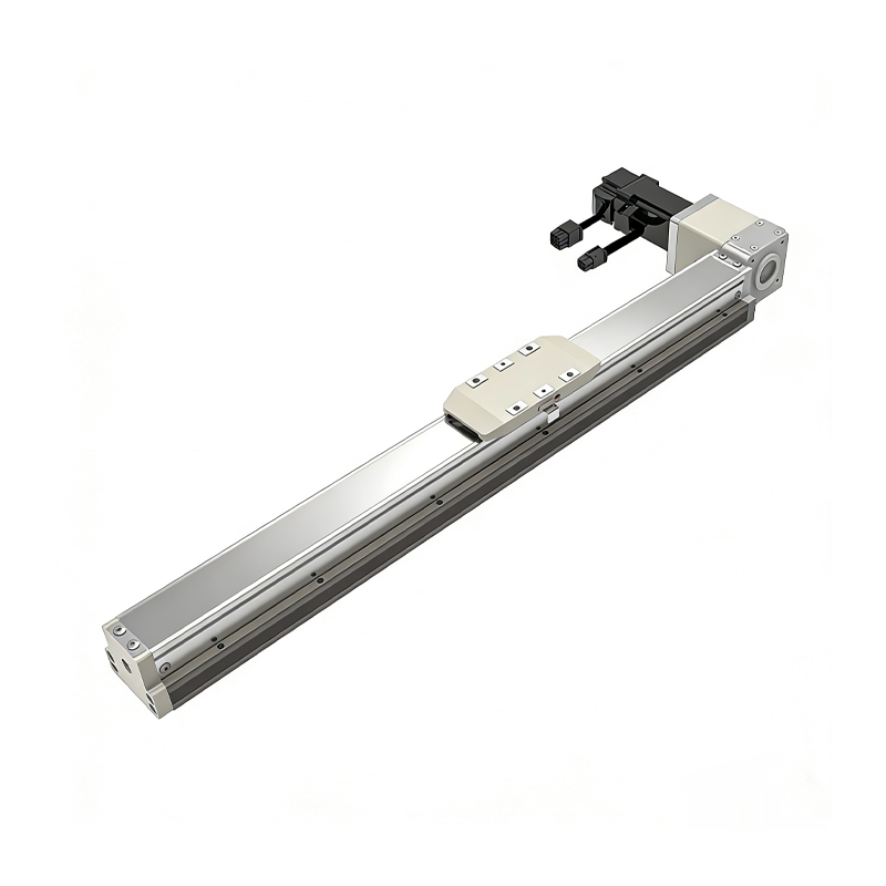 Belt Driven Dust-Proof Rail-Embedded Linear Module
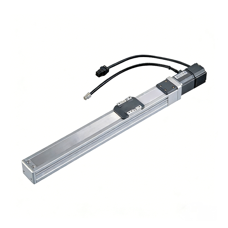 0.01mm High Precision Light Load Ball Screw Linear Module
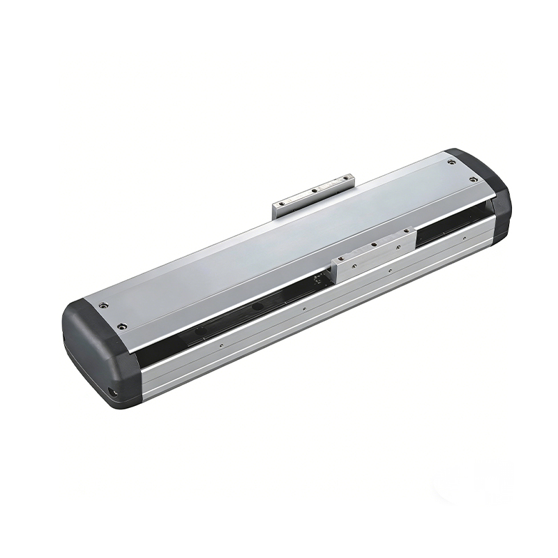 Ball Screw Linear Module with Built-in Sensor
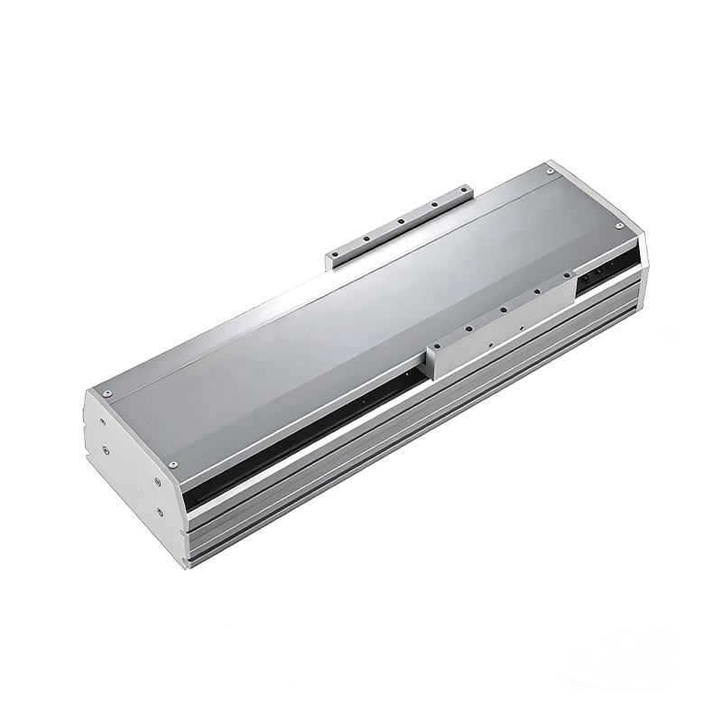 2000mm Long Stroke Ball Screw Linear Module
This 2000mm Long Stroke Ball Screw Linear Module is customized for large-range linear movement automation tasks, support...
READ MOREThis 2000mm Long Stroke Ball Screw Linear Module is customized for large-range linear movement automation tasks, support...
READ MOREThis 2000mm Long Stroke Ball Screw Linear Module is customized for large-range linear movement automation tasks, support...
READ MOREThis 2000mm Long Stroke Ball Screw Linear Module is customized for large-range linear movement automation tasks, support...
READ MORE
If you are interested in our products, please leave us a message. We look forward to providing you with
professional services!
Innovation and transcendence make factory intelligent manufacturing efficient and convenient!
+86 186 2508 0683
19962977901
sales@sz-tys.com
Building 5, Suzhou Mudu International Science and Technology Innovation Park, Jinfeng South Road, Suzhou City, Jiangsu Province, China
