


 English
 Français
 русский
 عربى
عربى Español
 Deutsch
Tel
+86 186 2508 0683

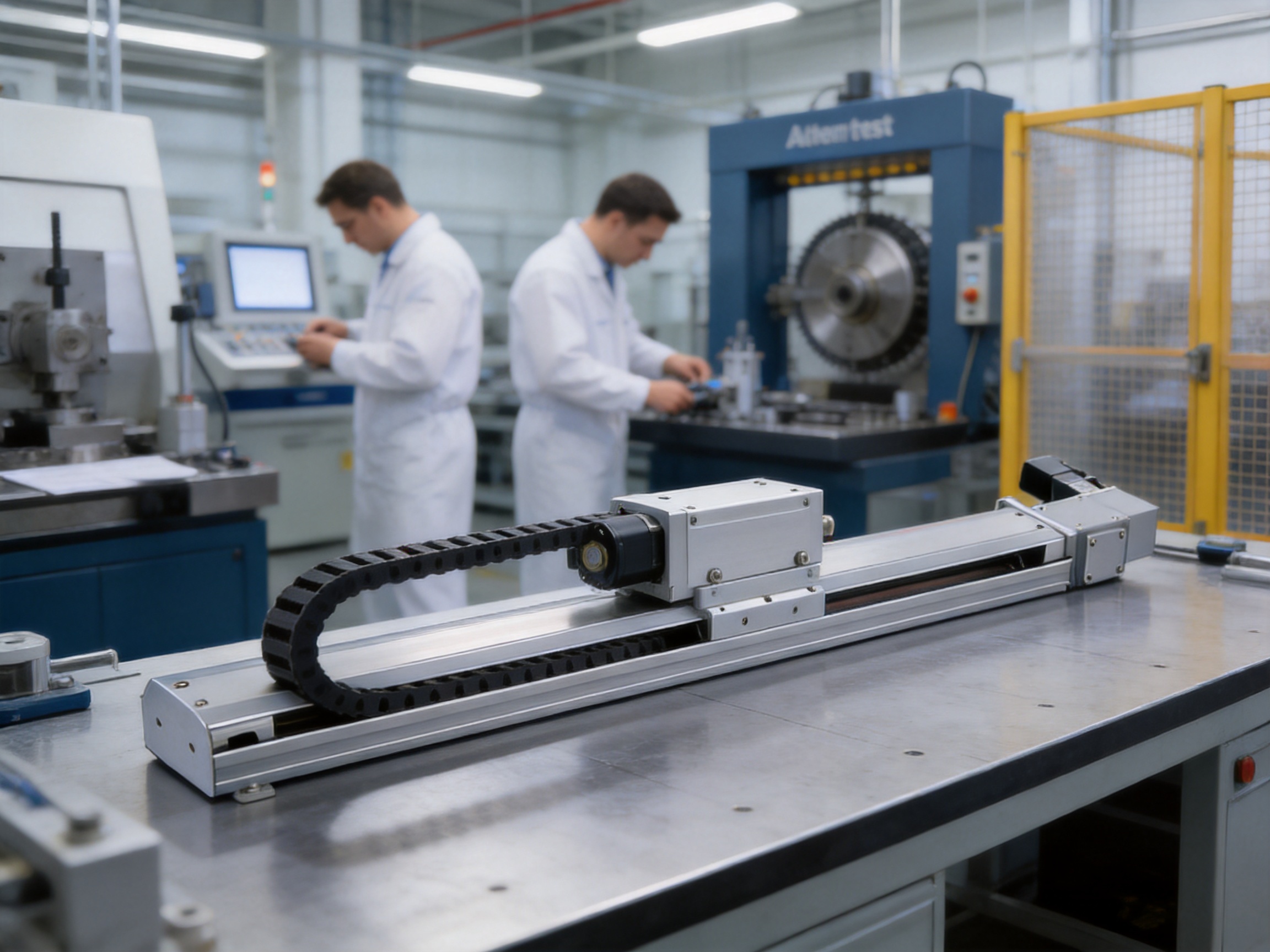
Modern automated production lines must move products quickly, accurately, and repeatedly while maintaining dependable performance over long operating cycles. As manufacturers increase throughput and reduce manual handling, the linear motion system becomes one of the most important components in the overall machine architecture. A linear module must accelerate and decelerate smoothly, support the required payload, maintain positioning precision, operate with acceptable noise, and integrate easily with servo motors, sensors, controllers, and additional axes.
The 2080 mm/s High-Speed Precision Belt-Driven Linear Module is designed for these demanding requirements. It combines a synchronous toothed-belt transmission, rigid aluminum extrusion, precision linear guidance, servo-motor compatibility, and a broad stroke range of 50 to 2550 mm. With a maximum speed of 2080 mm/s and repeat positioning accuracy of ±0.04 mm, the module is intended for high-speed sorting, handling, transfer, assembly, inspection, and packaging applications.
Its design is particularly suitable for industries where rapid movement and dependable cycle times directly influence productivity. These industries include 3C electronics, photovoltaic component manufacturing, food packaging, logistics automation, precision assembly, and general intelligent manufacturing. The module can be installed as a single axis or combined with other motion modules to create coordinated multi-axis equipment.
A belt-driven linear module converts rotary motion from a motor into controlled linear motion. In this product, the drive mechanism uses a synchronous toothed belt. The belt transfers motor torque to the moving carriage while maintaining positive engagement between the drive pulley and the belt teeth. This arrangement supports rapid travel and enables the module to reach a maximum speed of 2080 mm/s under suitable operating conditions.
The module is built around a high-strength aluminum extrusion. The extrusion serves as the structural body, supports the guide system, and provides mounting surfaces for installation into automated equipment. Its compact design helps engineers reduce machine footprint without sacrificing the rigidity required for high-speed motion.
Precision linear guides and sliding blocks support the moving carriage. These guiding components help control lateral movement, reduce unwanted play, and provide stable travel along the axis. The guide arrangement is especially important when the module operates at high speed, because vibration, deflection, and carriage instability can negatively affect product quality and service life.
The unit is designed for use with AC servo motors. A servo motor allows the system designer to control speed, acceleration, deceleration, position, and torque through a suitable servo drive and motion controller. The module is therefore appropriate for applications requiring programmed motion profiles rather than simple constant-speed travel.
Although the product is categorized as a belt-driven linear module, the supplied specification information also lists ball-screw-related terminology, including a ball screw lead of 41.6 mm and a ball screw diameter of 15 mm. These entries should be confirmed with the supplier during configuration because the product description identifies a synchronous toothed-belt drive. Proper confirmation ensures that the final technical drawing, bill of materials, motor selection, and control parameters accurately match the ordered configuration.
| Specification | Value |
| Product type | High-speed precision belt-driven linear module |
| Maximum speed | 2080 mm/s |
| Repeat positioning accuracy | ±0.04 mm |
| Stroke range | 50 to 2550 mm |
| Stroke increment | 50 mm |
| Horizontal maximum payload | 10 kg |
| Vertical maximum payload | 3 kg |
| Rated thrust | 61 N |
| Servo motor output | 200 W |
| Linear guide size | W20 × H18 mm |
| Specified service life | 10,000 km under normal conditions |
The combination of speed, accuracy, payload, and stroke makes this module suitable for equipment designers who need a balanced solution rather than a component optimized for only one performance parameter. A very high-speed axis with insufficient rigidity may create vibration, while a highly rigid axis that moves too slowly may limit production capacity. This design aims to combine fast travel with stable guidance and practical installation flexibility.
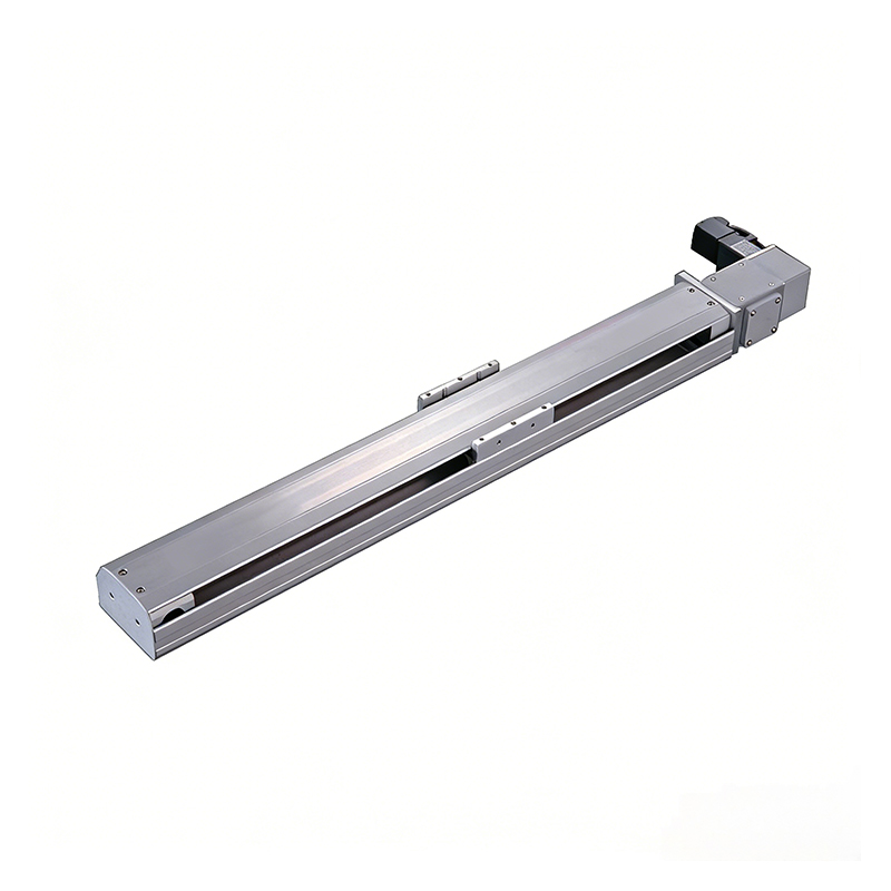
2080mm/s High-Speed Precision Belt Driven Linear Module
The most visible advantage of the module is its maximum speed of 2080 mm/s. High linear speed allows the carriage to complete transfer movements in less time, particularly when the working stroke is long or when the application includes frequent pick-and-place cycles. In a sorting line, for example, the axis can rapidly position a gripper, suction tool, or product carrier. In a packaging machine, it can support fast product alignment, feeding, or inspection operations.
High speed should not be considered separately from acceleration and deceleration. A productive motion profile must also control jerk, vibration, and settling time. The synchronous belt drive, precision guide system, and servo motor interface provide a foundation for developing controlled motion profiles. Machine builders can adjust acceleration, deceleration, and position control parameters according to payload, stroke, tooling, and cycle requirements.
Belt transmission is often selected for high-speed applications because it can deliver rapid travel without the rotating screw limitations associated with some conventional screw-driven designs. A belt drive also supports long travel distances without requiring a very long precision screw. This can simplify the mechanical design for applications that need a stroke approaching or exceeding two meters.
In practical operation, the maximum speed is influenced by several factors. These include payload, cantilever distance, installation orientation, acceleration, belt tension, tooling mass, environmental conditions, and the selected motor and drive. The stated maximum should therefore be treated as a rated performance reference rather than a universal operating value for every configuration. A complete application review is recommended before selecting a maximum production speed.
The module provides repeat positioning accuracy of ±0.04 mm. Repeatability is particularly important in automated processes that perform the same movement many times. Examples include placing electronic components, aligning photovoltaic parts, transferring trays, positioning packaging materials, and moving inspection fixtures.
Repeat positioning accuracy indicates how closely the axis can return to a commanded position under defined conditions. Actual results depend on servo tuning, load variation, mechanical installation, temperature, belt condition, sensor resolution, and the rigidity of the external machine structure. For this reason, system-level accuracy should be validated after the module is installed and integrated with the final tooling.
The use of precision linear guides helps stabilize the carriage and reduces unwanted lateral movement. A rigid aluminum extrusion helps limit structural deformation during acceleration and deceleration. Together with a correctly tensioned synchronous belt and a properly configured servo system, these features support consistent positioning performance in repetitive production.
For applications requiring higher process accuracy than the basic axis specification provides, engineers can combine the module with external measuring devices, vision systems, precision end-effectors, or secondary fine-adjustment mechanisms. The module can then provide fast coarse positioning while another mechanism performs final alignment.
The high-strength aluminum extrusion is a major part of the module’s mechanical design. Aluminum provides a useful balance of low weight, corrosion resistance, machinability, and structural performance. Reducing the moving mass of the axis can help the servo motor accelerate the carriage more efficiently, particularly in applications with frequent starts and stops.
The extrusion is designed to maintain a compact overall profile while providing mounting surfaces for the guide system and machine frame. A compact module can be useful when space is restricted, when multiple axes must be arranged close together, or when the machine requires a clean and organized layout around the working area.
Structural rigidity is essential for high-speed movement. If the body bends excessively, the carriage may experience vibration or positioning deviation. If the supporting machine frame is not sufficiently rigid, the performance of the linear module may also be reduced. The best results are achieved when the module is mounted on a level, stable, and accurately aligned base with suitable support spacing.
The aluminum extrusion also helps simplify equipment assembly. Standardized mounting surfaces allow the module to be attached to frames, brackets, gantries, and other automation components. The product can be configured with the motor on different sides or positions, including right-side, right-upper-side, right-lower-side, left-side, left-upper-side, and left-lower-side arrangements. These options allow designers to adapt motor placement to the available machine space.
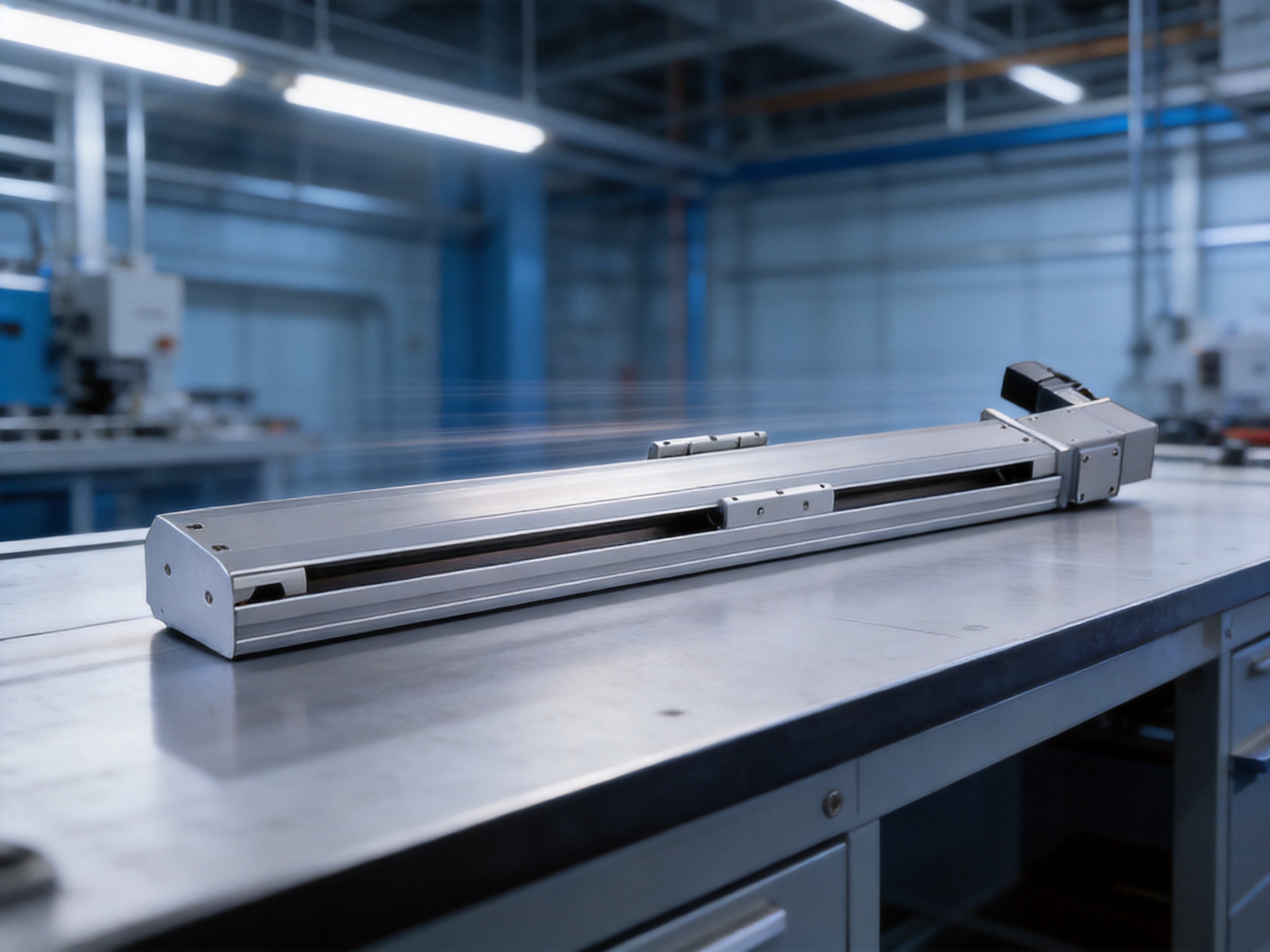
The integrated high-rigidity linear guide is specified as W20 × H18 mm. The guide and sliding block support the moving carriage while resisting the forces and moments generated by the load and tooling. Stable guidance reduces carriage oscillation and contributes to smooth travel, especially during rapid acceleration and deceleration.
Linear guidance also influences noise and maintenance. A properly installed guide with appropriate lubrication can operate smoothly and with reduced mechanical friction. The guide system must be kept clean, particularly in applications involving dust, packaging particles, food residues, or abrasive materials. Protective covers or machine enclosures may be necessary when the working environment contains contaminants.
When engineers select the module, they should consider the direction of the load, the distance between the load center and the carriage surface, and the external forces created by acceleration. A payload that is within the stated mass limit may still exceed the allowable moment if it is positioned too far from the carriage. Therefore, payload evaluation should include both weight and overhang.
The stated maximum payload is 10 kg for horizontal installation and 3 kg for vertical installation. These values provide a useful starting point for application design, but they should not be interpreted as independent of tooling geometry or motion profile. A 10 kg load positioned close to the carriage may be acceptable in a horizontal arrangement, while a lighter load positioned far away may create a greater bending moment.
The supplied allowable-overhang data gives design references for horizontal and wall-mounted installations. For example, the horizontal installation table lists values for 5 kg, 8 kg, and 10 kg loads, while the wall-mounted table lists values for 4 kg, 7 kg, and 10 kg loads. These figures help engineers assess how far a load may extend from the guide or carriage under particular installation conditions.
The static loading moment values are listed as follows: MY 110 N·m, MP 110 N·m, and MR 120 N·m. These values describe the allowable moment references around different axes. The actual interpretation depends on the coordinate system and installation orientation shown in the supplier’s engineering drawings. Engineers should verify the coordinate definitions before using the values for final design approval.
| Design factor | Why it matters | Recommended engineering action |
| Payload mass | Determines motor torque, guide loading, and stopping behavior | Include the workpiece, tooling, cable chain, and fixtures |
| Overhang | Creates bending moments that may affect accuracy and guide life | Measure the center-of-gravity distance from the carriage |
| Installation direction | Changes effective load and motor requirements | Distinguish horizontal, vertical, wall-mounted, and inverted use |
| Acceleration | Creates dynamic force in addition to static weight | Calculate force using the planned acceleration profile |
| Tooling inertia | Can cause vibration during rapid starts and stops | Use controlled jerk and servo tuning |
| External moments | May exceed guide or carriage capacity even at low payload | Check MY, MP, and MR against the application geometry |
For safety and long-term reliability, the machine designer should apply an appropriate engineering margin. Continuous high-speed operation, frequent emergency stops, uneven loading, and harsh environmental conditions may require a lower practical load than the nominal maximum.
The available stroke range is 50 to 2550 mm, with a 50 mm selection interval. This range enables the module to serve both compact pick-and-place mechanisms and long-transfer systems. A machine builder can select a stroke that closely matches the required travel rather than using an oversized axis with unnecessary length and mass.
For each stroke selection, the product information provides dimensional parameters including L, A, M, N, and weight. The overall length L increases in accordance with the selected stroke. For example, the listed overall length begins at 360 mm for a 50 mm parameter and increases in 50 mm increments as the selected travel becomes longer. The corresponding weight also increases as the extrusion and belt assembly become longer.
This dimensional information helps engineers estimate machine footprint, support requirements, transportation weight, and mounting locations. Longer axes may require more support points or a stronger machine frame to prevent deflection. They may also require careful cable management to avoid drag or interference during rapid travel.
The product’s long-stroke capability is one of the areas where a belt-driven design can offer an advantage over some screw-driven alternatives. Long ball screws may experience critical-speed limitations, whip, or increased manufacturing and installation complexity. A synchronous belt can provide long travel with a relatively straightforward mechanical arrangement. However, the final choice between belt and screw transmission should always consider the required thrust, accuracy, contamination level, vertical load, and duty cycle.
The module is designed for a 200 W AC servo motor. The supplied motor options include Mitsubishi, Panasonic, and Delta configurations. This gives machine builders flexibility when standardizing their control platform across an entire production line.
| Motor brand | Motor model | Driver model | Power | Voltage | Brake configuration |
| Mitsubishi | HG-KN23J-S100 | MR-JE-20A | 200 W | 220 V AC | No brake, horizontal type |
| Panasonic | MHMF022L1U2M | MADLN15SE | 200 W | 220 V AC | No brake, horizontal type |
| Delta | ECM-B3M-C20602RS1 | ASD-B3-0221-L | 200 W | 220 V AC | No brake, horizontal type |
Servo motor compatibility offers several practical benefits. First, it allows the motion axis to be integrated with established automation architectures. Second, servo feedback supports accurate control of position and speed. Third, the motor and drive can be tuned to suit the inertia and load characteristics of the application. Fourth, the availability of several motor brands may help reduce procurement restrictions for international customers.
The listed motor configurations are identified as having no brake and being suitable for horizontal use. Vertical applications may require a brake or a separate safety mechanism to prevent the load from falling during power loss. The supplier should confirm the correct motor, brake, drive, cable, and control configuration for vertical or wall-mounted installations.
Position sensors and home sensors help the motion controller establish a repeatable reference position. The supplied information identifies sensor options including EE-SX672 NPN and FC-SPX303Z-2M NPN. These sensors can be used to detect the home position, define travel limits, or support machine initialization.
A reliable homing sequence is important in equipment that must recover accurately after startup, maintenance, or a power interruption. The sensor installation position should be protected from mechanical impact and contamination. The control system should also include suitable limit logic, emergency stop functions, overtravel protection, and fault monitoring.
Sensor compatibility must be confirmed with the selected controller and input circuit. NPN sensors typically require the correct wiring arrangement and input type. Engineers should verify voltage, current, connector style, cable length, shielding, and signal polarity before completing the electrical design.
The performance of a high-speed linear module depends not only on its design but also on how accurately it is manufactured and assembled. The manufacturer operates as a high-tech enterprise integrating research and development, production, and sales. Its capabilities include advanced design software, high-precision CNC machining centers, engineering development, assembly, testing, and application support.
The aluminum extrusion must be produced and processed with consistent dimensional accuracy. Mounting surfaces, guide reference areas, pulley supports, and motor interfaces require controlled machining. CNC processing helps maintain repeatable dimensions across different production batches. Accurate machining is important because small alignment errors can increase guide friction, belt wear, noise, and positioning deviation.
The linear guide mounting surfaces must be carefully prepared. The guide rail and sliding block should be aligned with the module body so that the carriage travels smoothly throughout the stroke. During assembly, technicians must control parallelism, fastener tightening, belt tension, pulley alignment, and carriage movement. These steps directly influence the final motion quality.
The synchronous belt must be correctly installed and tensioned. Excessive tension can increase bearing and guide loads, while insufficient tension can cause tooth engagement problems, backlash, vibration, or position errors. A controlled assembly process helps ensure that the belt operates within its intended condition.
The company’s production approach includes strict dynamic balancing and aging tests. Dynamic balancing helps identify abnormal vibration and unstable behavior during operation. Aging tests allow the assembled module to operate for a defined period so that early-stage mechanical issues can be detected before shipment. These tests are particularly valuable for products intended for continuous high-speed duty.
Inspection may include dimensional checks, manual travel checks, sensor verification, motor rotation tests, noise observation, speed testing, and repeat positioning evaluation. The exact inspection plan can vary according to customer requirements, order configuration, and application risk. For demanding projects, customers can request additional inspection records or acceptance criteria before production.
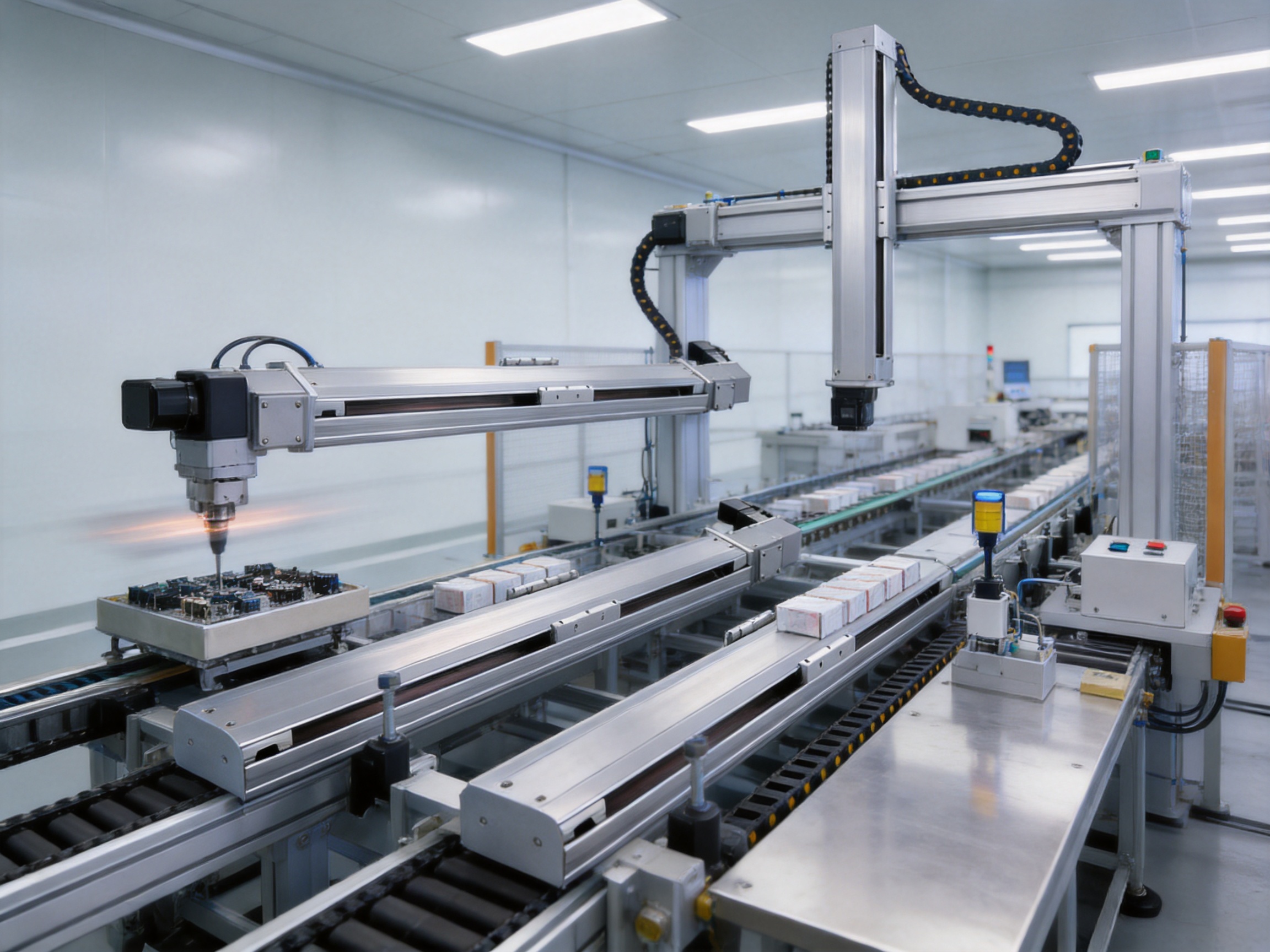
The module offers several advantages compared with conventional linear motion products, although the most appropriate solution depends on the application. Its first advantage is speed. A maximum travel speed of 2080 mm/s makes it suitable for rapid transfer operations where a slower screw-driven axis could extend cycle time.
Its second advantage is long-stroke flexibility. The 50 to 2550 mm stroke range allows the same product family to address multiple machine layouts. This can simplify engineering standardization and spare-parts management.
Its third advantage is configuration flexibility. Motor placement can be selected on different sides or positions, helping designers route cables and avoid interference with adjacent components. The module can also be used as a single axis or assembled into multi-axis systems.
Its fourth advantage is a balance between lightweight construction and structural rigidity. The aluminum extrusion keeps the system relatively manageable while providing a stable base for the guide and drive components. Lower moving mass can support responsive servo control and reduce energy demand during repeated movement.
Its fifth advantage is integration with widely used servo brands. Mitsubishi, Panasonic, and Delta options give machine builders more freedom to match the axis with existing control standards, spare-part policies, and service capabilities.
Its sixth advantage is testing for dynamic stability and operating life. The stated service life is 10,000 km when the product is used normally and according to the catalog specifications. This provides a useful reference for estimating maintenance intervals and expected operating duration, although actual life depends on load, speed, lubrication, contamination, installation, and duty cycle.
3C electronics production requires fast and repeatable movement of small parts, trays, housings, printed circuit boards, and inspection fixtures. The module can serve as a transfer axis for pick-and-place equipment, an alignment axis for assembly stations, or a positioning axis for camera inspection systems.
In electronic assembly, clean movement and controlled acceleration are essential. Sudden vibration can disturb small components or affect the image quality of a vision system. Servo control allows the machine builder to create suitable motion profiles for delicate products. The compact structure also supports dense equipment layouts where multiple stations are arranged in a limited floor area.
For testing equipment, the axis can move a product carrier between test points. For labeling or dispensing equipment, it can position a workpiece beneath a tool. For loading and unloading systems, it can transfer trays between conveyors, fixtures, and processing stations.
Photovoltaic manufacturing often involves large workpieces, repeated transfer operations, and strict requirements for careful handling. Linear modules can be used for material positioning, component transfer, inspection, and loading or unloading. The long-stroke options are useful when the machine must cover a broad working area.
Because photovoltaic components may be sensitive to impact, the motion system should be configured with controlled acceleration and suitable end-effectors. The rated horizontal payload of 10 kg may be appropriate for certain carriers and tools, but the actual application must account for the complete moving assembly. Engineers should also consider the size and center of gravity of panels or frames because a large lightweight workpiece can create substantial moments.
Food packaging equipment benefits from high-speed movement, repeatable positioning, and easy integration with sensors and conveyors. The module may be used to move packages, packaging tools, inspection devices, or handling mechanisms. Its fast travel can support short transfer times in sorting and packing operations.
Food production environments require careful attention to hygiene, cleaning procedures, and contamination control. The standard module should be evaluated against the specific environmental conditions of the machine. Protective covers, suitable lubrication practices, and appropriate placement may be required. The product should not be assumed to be suitable for direct washdown or food-contact applications unless the supplier confirms the relevant protection level and materials.
The module can be combined with other linear modules to create two-axis, three-axis, or more complex motion systems. A horizontal axis can be paired with a vertical axis for pick-and-place tasks. Two parallel modules can support a gantry arrangement for wider workpieces or improved load distribution. Additional rotary or linear axes can be added for assembly, dispensing, inspection, and robotic handling.
Multi-axis design requires careful consideration of moving mass. When one axis carries another axis, the motor must accelerate not only the workpiece and tooling but also the complete moving module. The system designer should recalculate payload, inertia, thrust, moment, and servo sizing for every axis.
Mechanical alignment is equally important. Parallel axes must be installed with controlled spacing and height. Misalignment can create binding, uneven guide loading, and increased motor demand. Cable chains and flexible conduits should be arranged to minimize drag and avoid placing side loads on the carriage.
The manufacturer’s experience with linear modules, robotic seventh axes, servo presses, electric cylinders, motion simulation platforms, and multi-degree-of-freedom systems supports the development of integrated automation solutions. This broader product knowledge can be valuable when a customer requires more than a standalone linear axis.
The installation base should be clean, level, and sufficiently rigid. Before tightening the mounting bolts, the module should be positioned and checked for straightness. Excessive distortion of the extrusion during installation can affect guide performance and increase travel resistance.
Loads should be mounted close to the carriage whenever possible. Reducing the distance between the center of gravity and the guide surface lowers the moment applied to the linear guide. If a long tool or offset fixture is unavoidable, the designer should calculate the resulting MY, MP, and MR values.
The motor and drive should be selected according to the real load profile rather than the payload mass alone. Acceleration, deceleration, duty cycle, vertical force, friction, and external resistance must all be considered. The servo drive should be tuned after installation with the final tooling and workpiece attached.
Home and limit sensors should be tested before automatic operation. The control program should include a safe homing sequence, soft limits, hard limits where appropriate, and an emergency stop circuit. Operators should not rely on software limits alone to protect personnel or equipment.
The catalog states a guaranteed service life of 10,000 km under normal use and in compliance with the stated specifications. This figure should be used as a design reference rather than a guarantee of identical life in every environment. High contamination, excessive load, poor alignment, incorrect belt tension, and aggressive acceleration can reduce service life.
Routine maintenance should include inspection of the belt, guide, carriage, fasteners, sensors, motor coupling or mounting, and cable routing. The belt should be checked for abnormal wear, tooth damage, fraying, contamination, or tension changes. The guide system should be lubricated according to the supplier’s recommended procedure and lubricant type.
Unexpected noise, vibration, increased motor current, positioning deviation, or uneven travel may indicate a developing problem. Early inspection can prevent secondary damage to the guide, pulley, belt, motor, or machine frame. Maintenance records should document operating hours, travel distance, lubrication, belt inspections, and replacement parts.
The standard specifications do not apply to ceiling-mounted inverted use. If the module must operate overhead or in another non-standard orientation, the customer should contact the supplier for confirmation. A special configuration may be required for load retention, brake selection, belt safety, lubrication, or structural support.
Automation projects often require more than a standard catalog product. Customers may need a particular stroke, motor position, sensor arrangement, mounting pattern, cable length, connector, belt specification, or multi-axis assembly. The manufacturer’s R&D and production capabilities make it possible to review these requirements during the design stage.
Engineering support may include load analysis, motor selection, layout review, stroke confirmation, installation orientation assessment, sensor configuration, and motion profile guidance. For complex systems, the supplier can help coordinate linear modules with electric cylinders, servo presses, robotic axes, or motion platforms.
Customization should be confirmed before production because changes to motor position, stroke, mounting holes, sensor brackets, or carriage design may affect delivery time and technical documentation. Customers should provide payload, center of gravity, travel, speed, acceleration, installation direction, duty cycle, environment, and control-system information for an accurate recommendation.
Suzhou Tongyousheng Electronic Technology Co., Ltd. was established in 2013 and focuses on the research, development, production, and sales of automation equipment and components. Its product portfolio includes electric cylinders, linear motion modules, linear motor modules, servo presses, robotic seventh axes, six-degree-of-freedom platforms, and multi-degree-of-freedom motion systems.
The company’s capabilities include experienced research and development personnel, advanced design software, high-precision CNC machining centers, and patented core technologies. These resources support the development of products that must combine mechanical precision, electrical control, structural reliability, and application-specific customization.
The company also collaborates with state-owned enterprises, defense technology institutions, and universities. Such cooperation can contribute to the exchange of technical knowledge, application research, control development, and the advancement of intelligent manufacturing technologies.
Its manufacturing approach emphasizes quality, reputation, innovation, and long-term development. By combining engineering design with in-house production and testing, the company can maintain closer control over critical factors such as component fit, machining accuracy, assembly consistency, and final performance verification.
For international customers, a supplier with capabilities across several automation categories can provide a more coordinated project experience. Instead of sourcing every axis, actuator, and motion platform from different vendors, customers may be able to build a broader solution through one technical partner.
Before ordering the high-speed belt-driven linear module, buyers should define the required stroke and confirm that the 50 mm selection interval meets the machine layout. They should calculate the total moving mass, including the workpiece, fixture, end-effector, cables, sensors, and any secondary axis carried by the module.
The required speed should be evaluated together with acceleration, deceleration, cycle time, and settling time. Maximum speed alone does not determine productivity. A slightly lower speed with faster settling may produce a better overall cycle time than a higher speed that generates excessive vibration.
Installation orientation must be clearly identified. Horizontal, wall-mounted, vertical, and inverted arrangements place different demands on the motor, brake, guide, belt, and machine structure. Vertical applications require particular attention to holding force and safety during power loss.
Buyers should also identify the preferred servo brand and control platform. The available Mitsubishi, Panasonic, and Delta options provide a starting point, but the final selection should match the customer’s existing drives, PLC or motion controller, communication network, safety system, and maintenance resources.
Environmental conditions should be documented. Temperature, dust, humidity, oil mist, cleaning chemicals, vibration, and food-processing requirements may affect the choice of protection and maintenance procedures. If the axis will operate in a specialized environment, the supplier should review the application before purchase.
The maximum listed speed is 2080 mm/s. The practical operating speed depends on payload, stroke, acceleration, installation orientation, tooling, belt condition, servo tuning, and machine-frame rigidity.
The specified repeat positioning accuracy is ±0.04 mm. Actual machine-level accuracy also depends on installation alignment, servo parameters, temperature, payload, sensor performance, and the rigidity of the external equipment.
The maximum listed payload is 10 kg for horizontal installation and 3 kg for vertical installation. The allowable payload must also be checked against overhang, center-of-gravity position, acceleration, and the specified static moment values.
Stroke selections range from 50 to 2550 mm in 50 mm increments. Overall length and product weight increase with the selected stroke.
The supplied options include 200 W AC servo motors from Mitsubishi, Panasonic, and Delta. The listed configurations are no-brake horizontal types. Vertical or special-orientation applications should be reviewed for brake requirements and other safety provisions.
Yes. The product information lists right-side, right-upper-side, right-lower-side, left-side, left-upper-side, and left-lower-side motor arrangements. The correct option should be selected according to cable routing, machine clearance, and neighboring components.
Yes. It can be combined with other linear modules to create multi-axis motion systems. When one axis carries another, engineers must recalculate moving mass, inertia, payload, moment, and servo requirements.
It can be considered for vertical applications within the stated 3 kg maximum vertical payload, but the final configuration must be reviewed carefully. Brake selection, load retention, emergency stopping, and power-loss safety are especially important for vertical motion.
The supplied information identifies EE-SX672 NPN and FC-SPX303Z-2M NPN sensor options. Wiring, voltage, connector, polarity, and controller compatibility should be confirmed before production.
The stated guaranteed service life is 10,000 km under normal use and in accordance with the catalog specifications. Actual life depends on loading, speed, contamination, lubrication, alignment, belt tension, and operating conditions.
The standard specifications do not apply to ceiling-mounted inverted use. Customers requiring this arrangement should request a technical review and confirmation of the appropriate configuration.
Customers should provide the required stroke, payload, center-of-gravity position, speed, acceleration, installation orientation, duty cycle, environment, preferred motor brand, sensor requirements, and control-system details. This information helps the supplier select a suitable configuration.
The 2080 mm/s High-Speed Precision Belt-Driven Linear Module is designed for manufacturers seeking rapid, repeatable, and flexible linear motion in automated production equipment. Its key performance features include a maximum speed of 2080 mm/s, repeat positioning accuracy of ±0.04 mm, horizontal payload up to 10 kg, vertical payload up to 3 kg, and stroke options from 50 to 2550 mm.
The synchronous toothed-belt drive supports high-speed travel and long-stroke applications. The high-strength aluminum extrusion provides a compact structural foundation, while the W20 × H18 mm high-rigidity linear guide supports stable carriage movement. Compatibility with Mitsubishi, Panasonic, and Delta servo systems gives machine builders useful control-system flexibility.
Compared with conventional solutions, the module offers an attractive balance of speed, travel range, installation flexibility, structural performance, and integration potential. Its suitability is strengthened by the manufacturer’s R&D capabilities, CNC machining resources, assembly procedures, dynamic balancing, aging tests, and experience with a broad range of automation products.
For the best results, the module should be selected as part of a complete engineering review. Payload, moment, overhang, motor configuration, installation direction, control requirements, environmental conditions, and maintenance needs must all be considered. When properly specified, installed, and maintained, this linear module can support efficient motion systems for electronics, photovoltaic, packaging, robotics, and intelligent manufacturing applications.
1. Product specification information for the 2080 mm/s High-Speed Precision Belt-Driven Linear Module.
2. Manufacturer-provided dimensional, payload, moment, motor, sensor, and service-life data.
3. General principles of synchronous belt transmission and linear guide design for industrial automation.
4. General servo motor sizing practices for linear motion applications.
5. General guidelines for machine-frame rigidity, payload overhang, acceleration, and dynamic moment evaluation.
6. Company information and manufacturing capability profile supplied for Suzhou Tongyousheng Electronic Technology Co., Ltd.
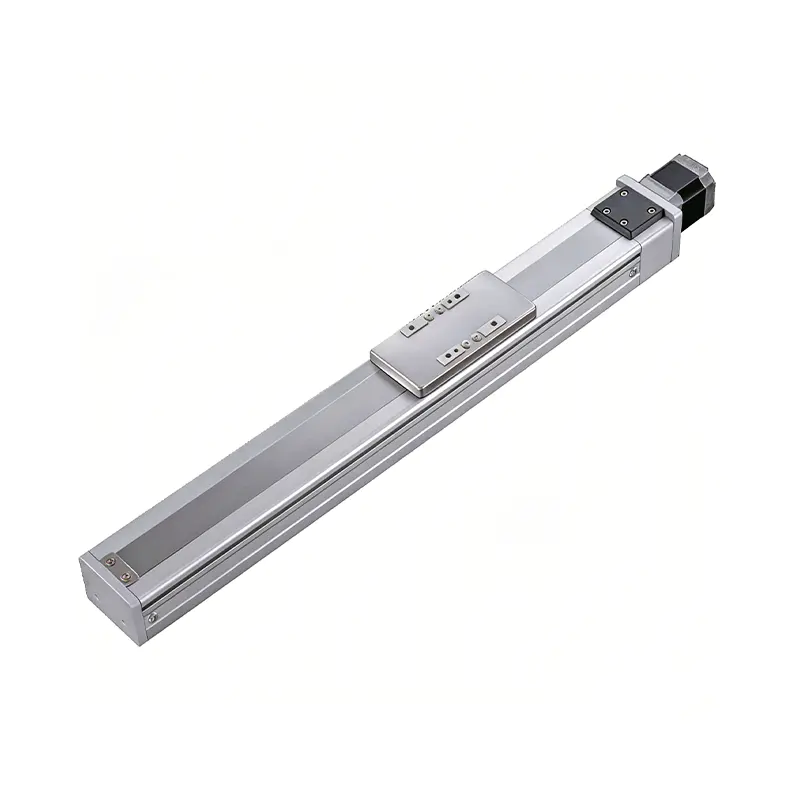 0.01mm High Precision Ball Screw Driven Rail-Embedded Linear Module
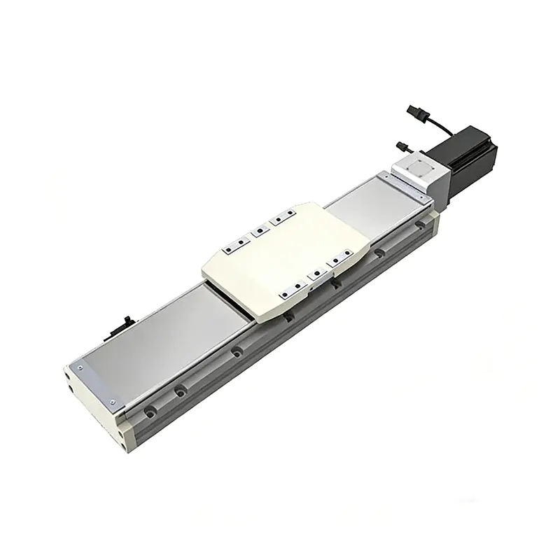 Heavy Load Ball Screw Driven Rail-Embedded Linear Module
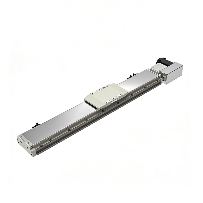 110KG Load Long Stroke Rail-Embedded Linear Module
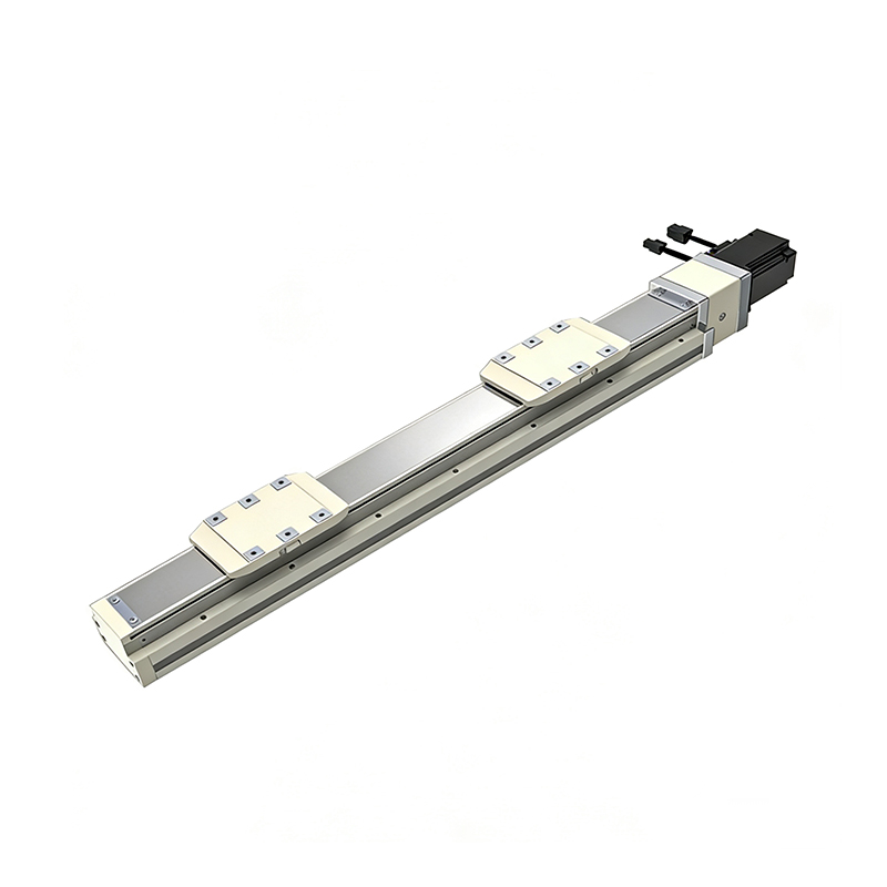 Dual-Slider High Precision Rail-Embedded Linear Module
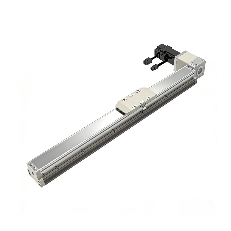 Belt Driven Dust-Proof Rail-Embedded Linear Module
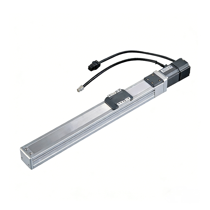 0.01mm High Precision Light Load Ball Screw Linear Module
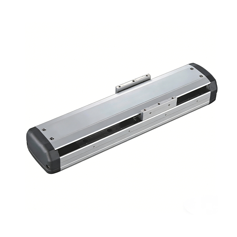 Ball Screw Linear Module with Built-in Sensor
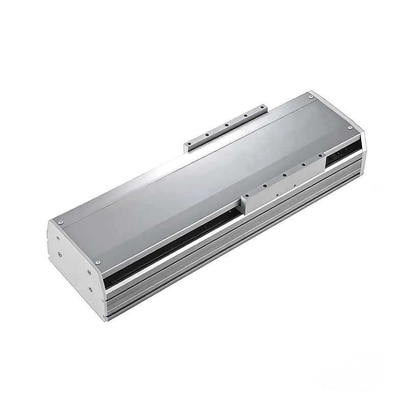 2000mm Long Stroke Ball Screw Linear Module
This 2000mm Long Stroke Ball Screw Linear Module is customized for large-range linear movement automation tasks, support...
READ MOREThis 2000mm Long Stroke Ball Screw Linear Module is customized for large-range linear movement automation tasks, support...
READ MOREThis 2000mm Long Stroke Ball Screw Linear Module is customized for large-range linear movement automation tasks, support...
READ MOREThis 2000mm Long Stroke Ball Screw Linear Module is customized for large-range linear movement automation tasks, support...
READ MORE
If you are interested in our products, please leave us a message. We look forward to providing you with
professional services!
Innovation and transcendence make factory intelligent manufacturing efficient and convenient!
+86 186 2508 0683
19962977901
sales@sz-tys.com
Building 5, Suzhou Mudu International Science and Technology Innovation Park, Jinfeng South Road, Suzhou City, Jiangsu Province, China
