


 English
 Français
 русский
 عربى
عربى Español
 Deutsch
Tel
+86 186 2508 0683

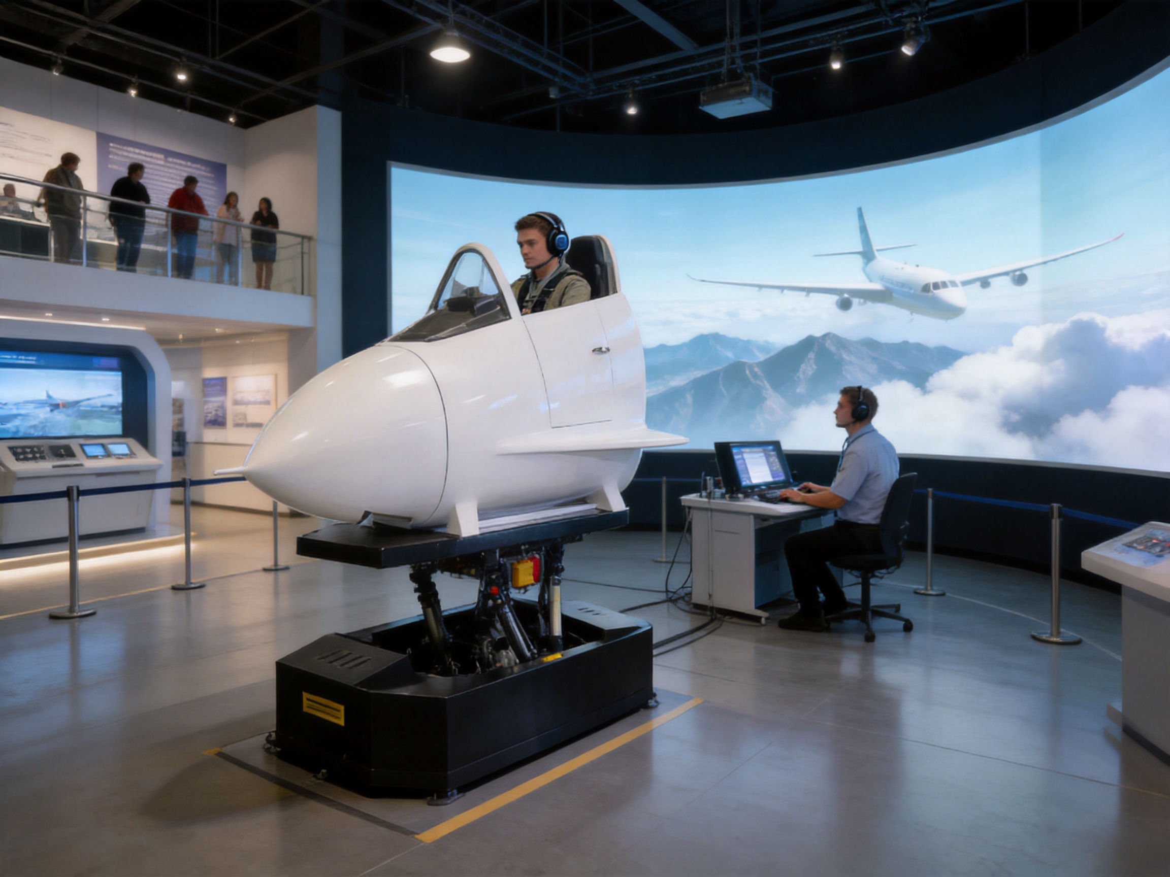
Flight simulation has evolved from a visual training aid into a highly integrated motion, control, and data-feedback environment. Modern users expect more than a projected cockpit scene. They expect the platform to reproduce the physical cues associated with acceleration, attitude changes, turbulence, landing, turning, climbing, and descending with sufficient precision to support training, education, exhibition, and entertainment. A high-precision six-degree-of-freedom flight simulation platform addresses this demand by combining three rotational movements and three linear movements in one coordinated system.
The platform described in this article is designed for professional flight simulation training centers, aviation exhibitions, science museums, educational institutions, commercial entertainment venues, and immersive experience projects. Its mechanical structure, EtherCAT-based control architecture, servo drive technology, high-dynamic ball screw concept, and configurable software provide a foundation for accurate and repeatable motion. At the same time, its broad range of travel, speed, load, and installation options allows the system to be adapted to different cockpit formats and application environments.
Unlike a fixed-base simulator, a six-degree-of-freedom motion platform can physically move the user or cockpit in pitch, roll, yaw, lateral displacement, longitudinal displacement, and vertical lift. These coordinated movements help convert digital flight data into physical motion. The result is a more convincing relationship between what the user sees, hears, and feels.
A six-degree-of-freedom flight simulation platform is a motion system capable of controlling an object in six independent but coordinated directions. The first three are rotational: pitch, roll, and yaw. The remaining three are translational: movement along the lateral, longitudinal, and vertical axes.
Pitch represents rotation around the lateral axis. It enables the platform to simulate nose-up and nose-down attitudes, such as climbing, descending, takeoff rotation, and landing approach. Roll represents rotation around the longitudinal axis. It is used to reproduce banking during turns, crosswind correction, and aircraft attitude changes. Yaw represents rotation around the vertical axis and can support directional changes, coordinated turns, and other horizontal-orientation effects.
Lateral displacement moves the platform from side to side. Longitudinal displacement moves it forward and backward. Vertical lift raises or lowers the platform. These linear motions can be used to reproduce acceleration cues, turbulence effects, runway movement, elevation changes, and special effects that complement the aircraft’s visual and audio environment.
The six axes do not operate independently during normal simulation. A flight maneuver generally requires several axes to move at the same time. For example, a banked turn may involve roll, yaw, lateral translation, and a carefully managed pitch response. The control system must therefore calculate and coordinate multiple actuators while maintaining smooth trajectories and preventing unwanted vibration or abrupt changes.
The platform is available with configurable motion ranges to suit different cockpit sizes, payloads, venue layouts, and simulation objectives. The stated rotational range for pitch, roll, and yaw is generally between ±5° and ±60°. This range allows the system to be specified for compact training applications or for more expressive motion effects in immersive commercial installations.
| Motion axis | Typical range | Maximum speed | Acceleration | Positioning accuracy | Repeat positioning accuracy |
|---|---|---|---|---|---|
| Pitch | ±5° to ±60° | Up to 50°/s | 100°/s² | 0.03° | 0.03° |
| Roll | ±5° to ±60° | Up to 50°/s | 100°/s² | 0.03° | 0.03° |
| Yaw | ±5° to ±60° | Up to 50°/s | 100°/s² | 0.03° | 0.03° |
| Lateral displacement | ±10 mm to ±450 mm | Up to 1,000 mm/s | Up to 2.0 g | 0.03 mm | 0.01 mm |
| Longitudinal displacement | ±10 mm to ±450 mm | Up to 1,000 mm/s | Up to 2.0 g | 0.03 mm | 0.01 mm |
| Vertical lift | ±10 mm to ±800 mm | Up to 1,000 mm/s | Up to 2.0 g | 0.03 mm | 0.01 mm |
The values in the table describe the available technical range rather than a single fixed configuration. Actual performance depends on the selected actuator model, payload, platform geometry, motion profile, cockpit structure, safety settings, and operating environment. This configurable approach is important because a compact museum simulator has different requirements from a full-size training cockpit or a high-throughput commercial attraction.
The rotational positioning accuracy is specified at 0.03°, with repeat positioning accuracy of 0.03°. For the linear axes, positioning accuracy is specified at 0.03 mm and repeat positioning accuracy at 0.01 mm. Such precision supports smooth reproduction of programmed motion profiles and improves the consistency of repeated training exercises or demonstration sequences.
Linear motion speeds can reach up to 1,000 mm/s, while the rotational axes can reach up to 50°/s. The acceleration capacity of up to 2.0 g on the linear axes provides substantial dynamic capability when the system is properly configured and the motion cueing strategy is correctly tuned. In practical use, the selected operating acceleration is normally adjusted according to user comfort, payload, cockpit structure, and the intended level of realism.
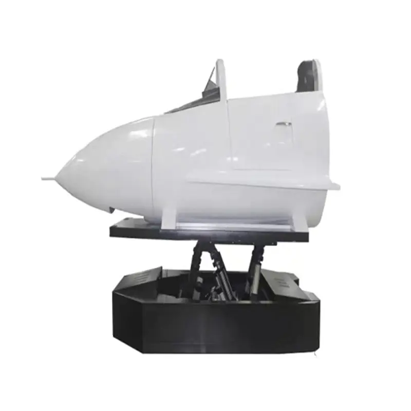
High Precision Six Degrees of Freedom Flight Simulation Platform
The platform is based on a coordinated actuator architecture designed to create accurate spatial movement while maintaining structural stability. Electric cylinders or related servo-driven linear actuators form the main motion elements. These actuators convert rotary motor output into controlled linear displacement and are integrated into the platform through mechanical joints and support structures.
The available technical specifications indicate a broad actuator range. Screw diameters may range from 12 mm to 80 mm, lead screws may range from 5 mm to 32 mm, and effective stroke or range may range from 70 mm to 800 mm depending on the selected model. Motor power can range from approximately 400 W to 22 kW, with rated output from 1 kN to 150 kN. These ranges allow the motion system to be matched to different platform weights and effective loads.
| Technical item | Available range or specification |
|---|---|
| Actuator form | Backtrack or direct connection |
| Application size | Approximately 0.5 to 8 m² |
| Motor power | 400 W to 22 kW |
| Screw diameter | 12 mm to 80 mm |
| Lead screw | 5 mm to 32 mm |
| Effective range | 70 mm to 800 mm |
| Rated output | 1 kN to 150 kN |
| Effective load | 2,000 kg to 15,000 kg, depending on configuration |
| Motor speed range | 1,500 to 3,000 rpm |
| Torque | 1.27 Nm to 140 Nm |
| Rated linear speed | Approximately 133 to 1,000 mm/s |
| Supply voltage | Single-phase or three-phase |
| Noise | Below 65 dB under specified conditions |
| Average trouble-free working time | More than 6,000 hours |
The high-dynamic ball screw concept is a central part of the mechanical design. Ball screws are widely used in precision motion systems because rolling contact can provide efficient transmission, controlled backlash, and good repeatability when properly selected, preloaded, lubricated, and aligned. In a flight simulation platform, the actuator must respond quickly to command changes while supporting substantial static and dynamic loads. A carefully engineered ball screw assembly helps balance these requirements.
Mechanical joints are also important. The available installation options include front and rear fork hinges, flange connections, and trunnion arrangements. These options make it possible to adapt the actuator to the selected platform frame and kinematic geometry. The correct joint arrangement affects load distribution, angular freedom, maintenance access, and the ability of each actuator to follow the commanded trajectory without excessive side loading.
The mechanical structure must be designed as a complete system rather than as a collection of individual cylinders. Structural stiffness, joint clearance, center of gravity, actuator alignment, bearing selection, emergency stops, cable routing, and access for inspection all influence the final motion quality. The manufacturer’s experience in electric cylinders, linear motion modules, linear motor modules, servo presses, and multi-degree-of-freedom platforms supports this system-level approach.
Many basic entertainment motion seats provide only one, two, or three movement directions. They may tilt the user, vibrate the seat, or create a simple heave effect, but they cannot reproduce a complete spatial attitude. A six-degree-of-freedom platform has a larger motion vocabulary. It can combine attitude changes with translation and therefore offers more flexibility for aircraft training, research demonstrations, and immersive simulation.
Electric servo actuation offers several practical benefits compared with systems that rely on less flexible mechanical or fluid-based arrangements. Motion commands can be generated, monitored, adjusted, and repeated through software. Electric cylinders can also provide controlled acceleration and deceleration, programmable profiles, and direct feedback to the control system.
Compared with a purely mechanical motion mechanism, a servo-controlled electric platform is easier to integrate with digital flight data, virtual-reality systems, visual systems, and external measurement equipment. Compared with a hydraulic system, an electric design can simplify power-unit requirements, reduce the risk of fluid leakage, and support a cleaner installation environment. The best choice still depends on load, duty cycle, speed, and application requirements, but the electric architecture is particularly attractive for venues that value precise control and relatively straightforward maintenance.
A simulator used for instruction or repeated public demonstrations must deliver consistent motion. If the same programmed scenario produces a different response every time, it becomes difficult to evaluate performance or maintain a predictable visitor experience. The specified positioning and repeat positioning accuracy help the platform reproduce defined motion cues with a high degree of consistency.
Repeatability also supports commissioning. Engineers can record a motion profile, adjust the algorithm, test it again, and compare results. This process is useful when integrating a new cockpit, changing the visual software, modifying the payload, or developing special effects for an exhibition.
A single fixed platform model cannot meet every application need. The platform’s range of motor powers, rated outputs, screw dimensions, travel lengths, angular ranges, and load capacities enables project-specific design. The system can be configured for relatively compact installations or for larger platforms supporting substantial cockpit and passenger loads.
This scalability is an advantage over standardized low-cost motion products that offer limited adjustment. A customer can select the actuator and structural configuration according to the number of seats, cockpit mass, center of gravity, required motion envelope, operating frequency, and available floor space.
Noise is a major concern in museums, exhibition halls, training classrooms, and commercial venues. Excessive actuator noise can interfere with instructor communication, audio effects, and visitor comfort. The stated noise level of below 65 dB under specified conditions provides a useful target for venue planning. Actual sound pressure depends on speed, acceleration, load, installation, lubrication, enclosure, floor structure, and surrounding acoustics, but the design emphasis on low noise improves suitability for public-facing environments.
The platform is specified with an average trouble-free working time of more than 6,000 hours. This figure is an engineering reference rather than a guarantee of maintenance-free operation. Regular inspection, lubrication, fastener checks, servo tuning, sensor verification, and replacement of wear components remain necessary. Nevertheless, the specification reflects an emphasis on continuous operation and serviceability, which is important for training centers and commercial installations with frequent daily cycles.
The control system uses an EtherCAT bus architecture. EtherCAT is designed for high-speed, deterministic industrial communication and is well suited to synchronized multi-axis motion. In a six-degree-of-freedom platform, timing consistency is essential. If one actuator responds noticeably later than another, the platform may create unwanted vibration, inaccurate attitude, or an uncomfortable motion cue.
With a bus-based system, servo drives and motion-control components can exchange command and feedback data through an organized network. The controller can coordinate the actuator positions, velocities, and acceleration profiles while monitoring operating status. The architecture also supports system diagnostics and simplifies the connection of multiple axes compared with extensive point-to-point wiring.
The stated system response frequency is 0 Hz to 20 Hz. This range is relevant to the generation and handling of motion cues, although the final experience depends on the controller, actuator bandwidth, software filtering, platform resonance, payload, and motion-cueing algorithm. A response frequency specification should therefore be evaluated together with practical test data and the customer’s intended simulation scenarios.
Core hardware is produced in-house according to the supplied technical information. In-house development can improve coordination between mechanical design, electrical control, servo tuning, and application software. It may also allow the manufacturer to respond more quickly when a customer requires a revised actuator configuration, a customized interface, or a specific control function.
A motion platform is only as effective as the software that translates simulated flight behavior into physical movement. The flight model may generate data for acceleration, angular velocity, attitude, altitude, turbulence, landing impact, and other events. The platform control system must filter and transform these signals into safe and meaningful actuator commands.
The control software is described as supporting non-calibrated operation and a self-developed core algorithm refined through repeated optimization. In this context, non-calibrated operation should be understood as a software approach intended to reduce or simplify routine calibration requirements. The actual commissioning process still needs to verify mechanical zero positions, sensor feedback, actuator limits, load distribution, and safety interlocks.
A suitable motion-cueing algorithm must consider the limits of the platform. An aircraft may experience acceleration values that cannot be reproduced directly by a physical motion system. The algorithm therefore selects cues that preserve the user’s perception of movement while keeping the platform inside its travel and speed boundaries. It may use tilt coordination, washout filtering, acceleration scaling, rate limiting, and other techniques to create a convincing response.
The platform can support programmable motion modes and flexible scene docking. Programmable modes are useful for flight training exercises, museum demonstrations, product presentations, and entertainment content. Scene docking allows the motion system to be connected with visual content, flight software, audio systems, cockpit instruments, virtual-reality equipment, or other external applications.
Optional matching algorithms and special-effects modules can be added according to the project. These may include customized turbulence sequences, runway vibration, landing impact, wind effects, emergency scenarios, or synchronized movements for a particular aircraft model. The objective is not simply to maximize movement, but to produce movement that corresponds logically to the visual and simulated flight event.
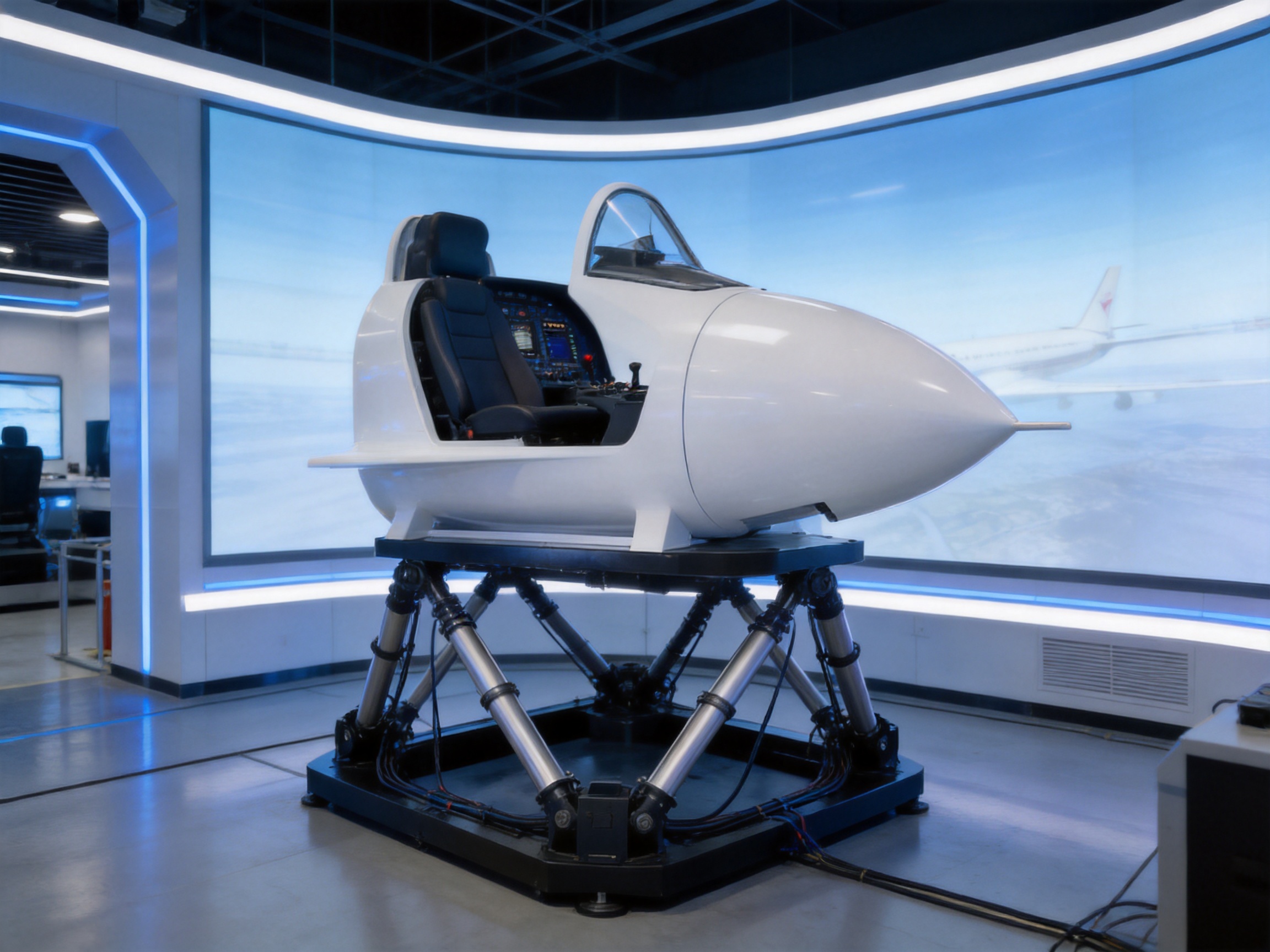
The manufacturer is a high-tech enterprise integrating research and development, production, and sales. Its product portfolio includes electric cylinders, linear motion modules, linear motor modules, servo presses, robotic seventh axes, and multi-degree-of-freedom platforms. This combination is relevant to the flight simulation platform because the system requires expertise in precision transmission, servo control, structural engineering, motion coordination, and industrial manufacturing.
Product development begins with application analysis. Engineers need to understand the cockpit dimensions, passenger capacity, effective load, center of gravity, motion envelope, duty cycle, floor conditions, safety requirements, and integration interfaces. The intended training or entertainment scenario also affects the motion strategy. For example, a professional training center may prioritize repeatability, data logging, and controlled acceleration, while a commercial venue may place greater emphasis on throughput, robust operation, visual impact, and simplified operator control.
Mechanical design software and simulation tools are used to evaluate the platform geometry and actuator arrangement. Design review should include the maximum and minimum actuator positions, joint angles, singularity risks, structural deflection, collision clearance, emergency stop behavior, and maintenance access. A well-designed kinematic layout reduces the risk of uneven loading and improves the ability of the actuators to produce smooth motion throughout the working envelope.
Advanced CNC machining centers support the production of precision mechanical components. CNC machining can be used for actuator housings, mounting brackets, joint components, flanges, support structures, and other parts that require controlled dimensions. Consistent machining quality is important because small dimensional errors can accumulate across a multi-axis mechanism. Accurate interfaces help maintain alignment and reduce unnecessary mechanical stress.
After machining, components require inspection. Depending on the part and tolerance, inspection may include dimensional measurement, thread verification, surface checking, runout testing, and verification of mounting interfaces. Critical assemblies such as ball screw units and actuator bodies need particular attention because alignment and preload directly influence noise, efficiency, repeatability, and service life.
Assembly is performed as a controlled engineering process rather than simply fastening parts together. Actuator alignment, bearing installation, screw lubrication, cable routing, encoder connection, limit-switch positioning, and fastener torque all affect the final result. The assembled platform must be checked for free movement, interference, abnormal noise, and correct response to manual and automatic commands.
Servo commissioning follows mechanical assembly. Engineers verify motor direction, encoder feedback, acceleration and deceleration limits, position limits, emergency stop functions, network communication, and synchronization between axes. Motion profiles are gradually increased from low-speed tests to the required operating range. This staged method helps identify mechanical or software issues before full-load operation.
The company’s core patents and accumulated experience provide a basis for continuing product development. Since its establishment in 2013, the organization has expanded from motion components and linear modules into electric cylinders, servo presses, six-degree-of-freedom motion platforms, algorithmic control software, and multi-degree-of-freedom linkage systems. This development path indicates an effort to build both component-level and system-level capabilities.
Quality control for a motion platform should cover incoming materials, machining, assembly, electrical integration, software configuration, and final testing. Important checks include actuator stroke, backlash, encoder feedback, motor temperature, load response, travel limits, communication stability, noise, vibration, and repeatability.
For a six-axis platform, final testing should also evaluate coordinated movement. Testing only one actuator at a time cannot reveal all system-level issues. Engineers should test combined pitch and roll, translation with rotation, maximum programmed travel, emergency deceleration, repeated cycles, and operation under representative payload conditions.
Long-duration testing is valuable for identifying thermal buildup, lubrication problems, cable fatigue, fastener loosening, and control drift. The supplied specifications note that the platform can operate continuously for more than 12 hours with the position drift of any one cylinder not exceeding 0.0025 m. This specification should be interpreted together with the test conditions, payload, ambient temperature, and motion profile. It nevertheless highlights the importance placed on stability during extended operation.
A moving cockpit carries significant mass and may be occupied by one or more people. Safety must therefore be integrated into the mechanical, electrical, and software design. The platform should include physical travel limits, software travel limits, emergency-stop circuits, controlled shutdown behavior, overload monitoring, fault alarms, and appropriate guarding or restricted-access measures.
Operator controls should make the system status easy to understand. A clear interface can show active motion mode, axis position, fault status, emergency-stop condition, communication status, and maintenance warnings. For training centers, instructors may require a rapid stop function that brings the platform to a safe condition without creating an unnecessary secondary hazard.
Load assessment is essential. The effective load includes the cockpit structure, seats, instruments, display equipment, passengers, cabling, and any additional equipment mounted above the moving frame. The center of gravity must be considered during design because an uneven or high center of gravity can increase actuator forces and affect stability.
Maintenance planning should include periodic inspection of ball screws, joints, bearings, mounting bolts, electrical connectors, sensors, and safety devices. Lubrication intervals should be defined according to the actuator design and operating conditions. Operators should also record abnormal noise, increased vibration, slower response, position errors, and recurring faults so that corrective action can be taken before a failure affects the training or commercial schedule.
Professional training organizations can use the platform to enhance cockpit procedures, orientation exercises, instrument familiarization, and scenario-based learning. Motion feedback may help trainees connect instrument indications and visual events with physical aircraft behavior. The platform can be integrated with training software and customized according to aircraft type, lesson plan, or instructor preference.
Motion should complement, not replace, the flight model and instructional content. A well-configured platform can provide useful physical cues while allowing the instructor to maintain control of the scenario, pause the exercise, repeat a maneuver, or adjust motion intensity for different levels of experience.
Museums and exhibitions often need an attraction that combines education with direct participation. A six-degree-of-freedom platform can demonstrate the principles of aircraft attitude, acceleration, control surfaces, and flight dynamics in an engaging format. Programmable scenes can be developed for school groups, public visitors, or special events.
For these venues, low noise, reliable operation, accessible controls, and safety are especially important. The platform’s configurable size and load range can help museums select a solution that fits their available space and expected visitor flow.
Immersive theaters, theme parks, aviation experiences, and simulation centers can use the platform to create motion-enhanced content. It can support single-seat or multi-seat cabins, depending on the selected structure and payload. Motion scenes may include takeoff, aerial combat, storm flight, space exploration, racing, or other experiences that benefit from coordinated physical movement.
Commercial venues normally require high availability and straightforward operation. A programmable control system can allow staff to select scenes, adjust intensity, monitor faults, and return the platform to a safe position. The system can also be synchronized with visual projection, head-mounted displays, sound systems, lighting, and environmental effects.
Universities, laboratories, and engineering schools can use the platform to study robotics, control algorithms, kinematics, human perception, and motion simulation. Because the system combines mechanical actuators with networked servo control, it can serve as a practical demonstration platform for industrial automation and mechatronics.
Researchers may also use the platform to evaluate motion-cueing methods, control-loop performance, sensor fusion, and the relationship between simulated acceleration and human perception. The programmable nature of the system provides a repeatable environment for experiments.
The platform can be supplied as a motion base or integrated with a complete cockpit structure. The choice depends on whether the customer already has a cockpit, intends to fabricate one independently, or requires a complete application solution. Mechanical interfaces should be defined at the beginning of the project to ensure that the cockpit frame, actuator joints, cable paths, and emergency access are compatible.
Software integration may involve a flight simulator, real-time visual system, virtual-reality engine, data acquisition system, or custom application. The required data can include aircraft attitude, angular velocity, linear acceleration, ground contact state, turbulence intensity, and other variables. The control software then converts these data into axis commands according to the selected motion profile.
Scene docking should be tested under realistic operating conditions. Latency between the visual event and physical movement can reduce immersion, so the integration process should evaluate data timing, communication delays, filtering, and synchronization. It is also important to define what happens if the external simulation software stops sending data. The motion system should enter a controlled safe state rather than continuing with undefined commands.
Project commissioning usually includes mechanical installation, electrical connection, network setup, software configuration, calibration verification, unloaded testing, loaded testing, operator training, and acceptance testing. A structured commissioning plan reduces installation risk and creates a record for future maintenance.
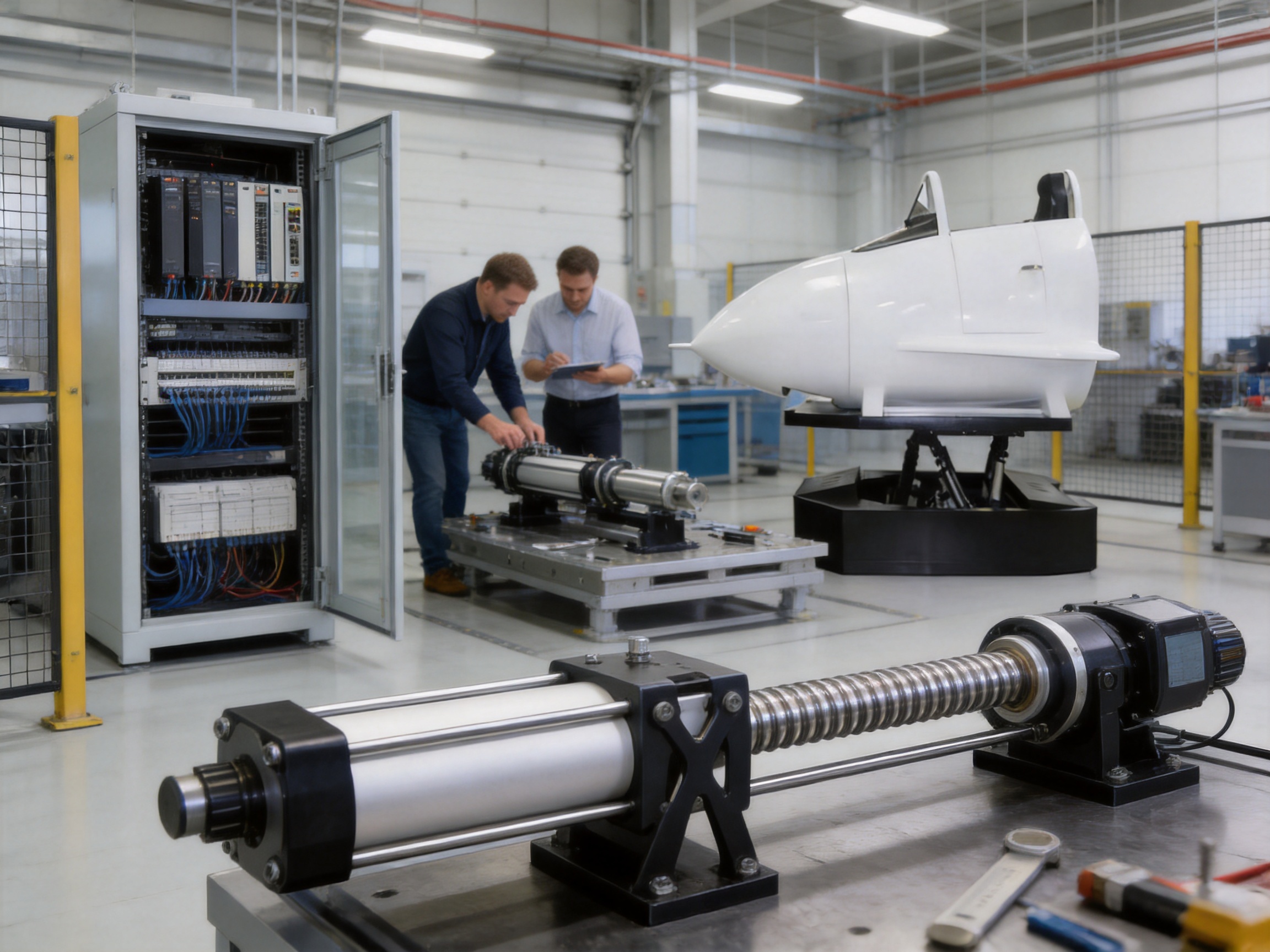
Customization is one of the main reasons to select an industrial motion-platform manufacturer instead of a standardized consumer motion product. The system can be designed around the required platform area, cockpit mass, passenger capacity, motion range, actuator output, motor power, and installation method.
Rotational limits can be selected within the available pitch, roll, and yaw range. Linear travel can be adjusted for lateral, longitudinal, and vertical movement. The customer may also specify the preferred power supply, mounting orientation, control interface, cockpit attachment method, and environmental requirements.
Motion profiles can be customized for different audiences. A training center may require conservative, highly repeatable cues that support instruction. A museum may prefer short, intuitive demonstrations with controlled motion intensity. An entertainment venue may request more dynamic special effects, provided that the final configuration remains within appropriate safety and comfort limits.
Software customization can include scene selection, user permissions, operator dashboards, data logging, fault reporting, external communication protocols, and special-effects algorithms. The platform manufacturer’s experience with control algorithms and motion-system integration can help shorten the development process for projects that require more than standard point-to-point movement.
Before installation, the customer should prepare a suitable foundation and confirm the available floor area, ceiling clearance, power supply, ventilation, access route, and safety perimeter. The installation area should support the static and dynamic loads generated by the platform. The floor should be sufficiently level and rigid to prevent unwanted structural movement.
Once the mechanical base is positioned, the platform is assembled and connected to its electrical cabinet, servo drives, control computer, safety circuits, and external simulation equipment. Cable chains or protected cable routes should be used to prevent bending fatigue and accidental contact with moving parts.
Initial commissioning begins with a low-speed inspection. Each axis is moved through a limited range while engineers check position feedback, direction, travel limits, noise, vibration, and mechanical clearance. Combined-axis testing follows after individual-axis behavior has been confirmed.
Maintenance should be organized around operating hours and cycle counts. A routine inspection may include cleaning, lubrication, joint inspection, connector checks, and confirmation of emergency-stop operation. Periodic service may include actuator backlash measurement, servo tuning, sensor verification, and inspection of structural fasteners.
Operators should avoid modifying motion parameters without authorization. Increasing speed or acceleration without reviewing payload, stability, and actuator capacity may affect safety and service life. Any change to the cockpit, seat arrangement, display equipment, or passenger capacity should be reviewed because it may change the center of gravity and total load.
The quality of a six-degree-of-freedom platform depends on more than the nameplate rating of its motors. The performance of the complete system is affected by transmission accuracy, structural stiffness, actuator alignment, servo response, software coordination, thermal behavior, and the quality of final commissioning.
A manufacturer with experience in electric cylinders understands the relationship between screw selection, motor torque, speed, load, efficiency, backlash, and service life. Experience in linear motion modules contributes knowledge of guide systems, mounting accuracy, cable management, and modular installation. Experience in servo presses contributes understanding of force control, precision positioning, overload protection, and industrial duty cycles.
Experience with linear motor modules and robotic seventh axes further supports the development of fast and coordinated motion systems. These technologies require reliable feedback, accurate trajectory control, and robust mechanical integration. The same principles are valuable in a six-degree-of-freedom simulation platform.
The company’s cooperation with state-owned enterprises, defense technology institutions, and universities also reflects an emphasis on technical collaboration and application development. Such cooperation can support the refinement of control algorithms, mechanical structures, simulation methods, and specialized motion solutions.
Before ordering a platform, buyers should define the intended application in detail. Important questions include the number of occupants, cockpit weight, total moving mass, desired pitch and roll range, required vertical lift, target speed, daily operating hours, available floor space, and preferred visual system.
| Selection factor | Questions to evaluate |
|---|---|
| Payload | What are the cockpit, equipment, passenger, and accessory weights? |
| Center of gravity | Where is the combined center of gravity relative to the motion base? |
| Motion range | How much pitch, roll, yaw, lateral, longitudinal, and vertical travel is required? |
| Operating cycle | How many hours and motion cycles will the platform run each day? |
| Venue | Is the system intended for training, education, exhibition, research, or entertainment? |
| Integration | Which flight simulator, visual system, cockpit, or external software must be connected? |
| Safety | What guarding, emergency-stop, access-control, and operator-training measures are required? |
| Maintenance | What inspection access, spare parts, lubrication, and service response are needed? |
| Environment | Are there special requirements for noise, temperature, dust, humidity, or public access? |
Buyers should request a configuration based on actual load and kinematic requirements rather than selecting an actuator solely by maximum speed or motor power. A complete technical review should verify whether the selected system can achieve the desired motion at the required payload and duty cycle.
For a training organization, the platform can increase the realism and flexibility of simulation exercises. Repeated scenarios can be delivered consistently, and instructors can adjust or replay motion sequences as needed. For an exhibition venue, the system can create a memorable interactive attraction that communicates aviation concepts through physical experience. For commercial entertainment, the platform can support differentiated content and a stronger sense of immersion than a fixed seat.
The ability to use programmable scenes also improves the long-term value of the installation. New flight scenarios, educational programs, seasonal content, or promotional experiences can be developed without replacing the entire motion base. The platform can therefore serve as a configurable hardware foundation for changing software content.
Its modular relationship with electric cylinders, servo motors, control software, and structural components can also simplify future upgrades. Depending on the original design, customers may be able to update software, replace selected components, add sensors, or modify the cockpit while retaining the main motion structure.
It means that the platform can control three rotational axes—pitch, roll, and yaw—and three linear axes—lateral displacement, longitudinal displacement, and vertical lift. These axes can operate separately or in coordinated combinations.
The platform can reproduce motion cues associated with acceleration, attitude changes, turbulence, and other flight events. It cannot physically reproduce every sustained acceleration experienced by a real aircraft. Motion-cueing software uses controlled translation, rotation, scaling, and filtering to create a convincing and safe physical representation.
The stated configurable range for pitch, roll, and yaw is approximately ±5° to ±60°. The final range depends on the selected design, cockpit structure, load, safety requirements, and application.
The stated ranges are approximately ±10 mm to ±450 mm for lateral and longitudinal displacement, and ±10 mm to ±800 mm for vertical lift. These values are configuration ranges rather than a guarantee that every axis will use its maximum travel simultaneously.
Rotational positioning accuracy is specified at 0.03°, with repeat positioning accuracy of 0.03°. Linear positioning accuracy is specified at 0.03 mm, with repeat positioning accuracy of 0.01 mm. Actual results depend on payload, temperature, actuator selection, installation, control settings, and maintenance condition.
EtherCAT provides a high-speed, deterministic communication architecture that is suitable for synchronized multi-axis control. It helps the controller coordinate servo drives and receive feedback from multiple actuators with consistent timing.
Yes, it can be designed as a motion base for an existing cockpit or integrated with a new cockpit structure. The engineering team needs information about cockpit dimensions, mass, center of gravity, mounting points, cable routing, and safety requirements before confirming compatibility.
It can be suitable for aviation exhibitions, museums, science centers, and commercial entertainment venues when properly configured with appropriate guarding, emergency-stop systems, operator controls, passenger restraints, and maintenance procedures. Public-use requirements should be reviewed during project design.
The technical information specifies noise below 65 dB under stated conditions. Actual noise can vary with speed, acceleration, payload, foundation, lubrication, enclosure, and surrounding acoustics. A site-specific evaluation is recommended for noise-sensitive venues.
Maintenance normally includes inspection of ball screws, bearings, joints, fasteners, sensors, cables, connectors, and safety systems. Lubrication and servo checks should follow the actuator manufacturer’s recommendations and the actual operating schedule.
Yes. The control software supports programmable motion modes, scene docking, optional matching algorithms, and special-effects modules. Custom scenes can be developed for training, education, exhibitions, or entertainment, subject to the mechanical and safety limits of the selected configuration.
A technical quotation normally requires the cockpit or cabin dimensions, total moving weight, passenger capacity, center of gravity, desired motion ranges, target speed and acceleration, operating hours, installation space, power supply, control interface, visual system, and intended application.
The high-precision six-degree-of-freedom flight simulation platform is a flexible motion solution for applications that require accurate, repeatable, and immersive physical movement. Its combination of pitch, roll, yaw, lateral displacement, longitudinal displacement, and vertical lift provides a wider motion envelope than conventional limited-axis systems. Servo-driven electric actuation, high-dynamic ball screw technology, EtherCAT communication, programmable software, and configurable mechanical structures support demanding simulation projects.
The platform’s advantages are especially relevant to buyers seeking more than a standard entertainment motion seat. Its broad actuator range, precision specifications, low-noise design target, extended operating capability, and compatibility with customized cockpit and software systems allow the platform to be adapted to training centers, aviation museums, educational institutions, research laboratories, and commercial venues.
Behind the product is a manufacturing organization with experience in electric cylinders, linear motion systems, servo presses, robotic axes, and multi-degree-of-freedom platforms. The combination of research and development, in-house core hardware, advanced CNC machining, control-algorithm development, system integration, and application-oriented customization provides a strong foundation for producing complete motion solutions rather than isolated components.
When correctly specified and commissioned, the platform can provide a reliable bridge between simulated flight data and human physical perception. It supports realistic training, engaging education, interactive exhibitions, and immersive entertainment while maintaining the precision and control expected from an industrial automation manufacturer.
1. International Organization for Standardization. ISO 9283, Manipulating Industrial Robots—Performance Criteria and Related Test Methods.
2. International Electrotechnical Commission. IEC 61158, Industrial Communication Networks—Fieldbus Specifications.
3. EtherCAT Technology Group. EtherCAT Communication Principles and Distributed Clock Concepts.
4. International Organization for Standardization. ISO 13849, Safety of Machinery—Safety-Related Parts of Control Systems.
5. International Organization for Standardization. ISO 12100, Safety of Machinery—General Principles for Design—Risk Assessment and Risk Reduction.
6. International Organization for Standardization. ISO 16368, Space Engineering and Simulation-Related Motion System Considerations.
7. Manufacturer-provided technical specifications for electric cylinders, servo motion systems, and six-degree-of-freedom platforms.
8. Manufacturer-provided information regarding motion-platform control software, manufacturing capabilities, application development, and system integration.
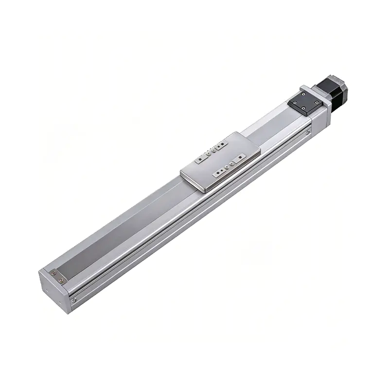 0.01mm High Precision Ball Screw Driven Rail-Embedded Linear Module
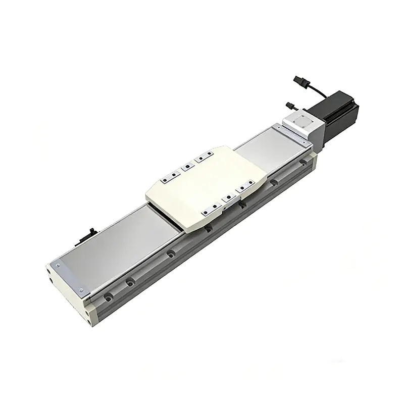 Heavy Load Ball Screw Driven Rail-Embedded Linear Module
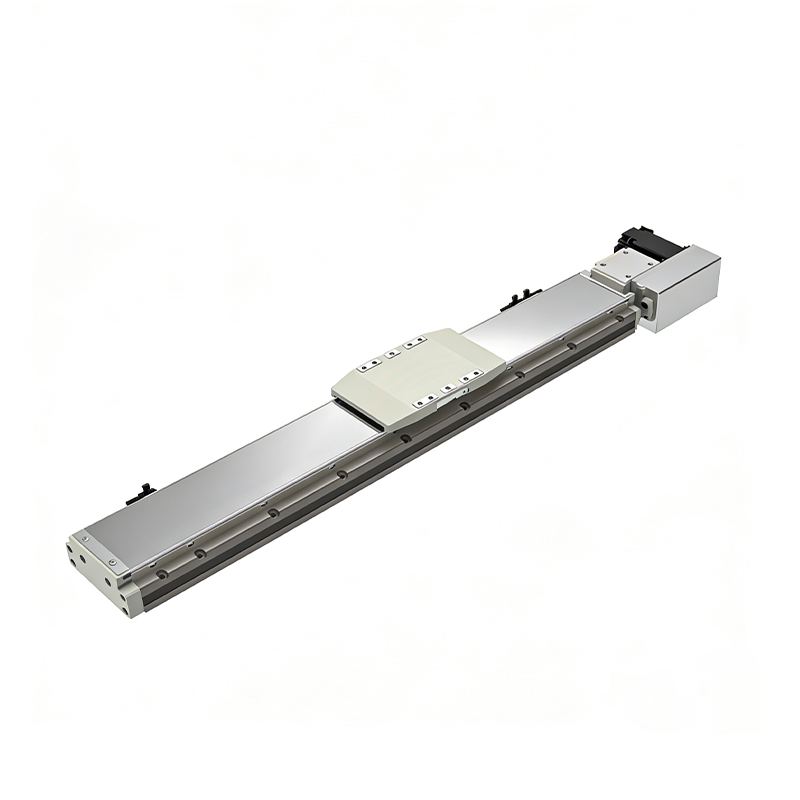 110KG Load Long Stroke Rail-Embedded Linear Module
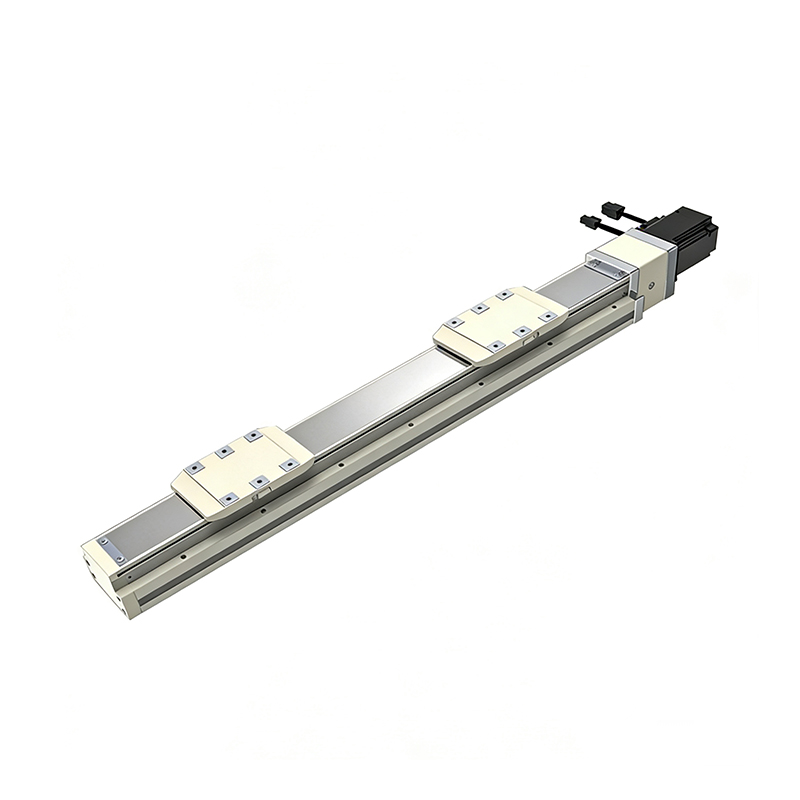 Dual-Slider High Precision Rail-Embedded Linear Module
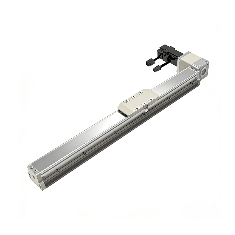 Belt Driven Dust-Proof Rail-Embedded Linear Module
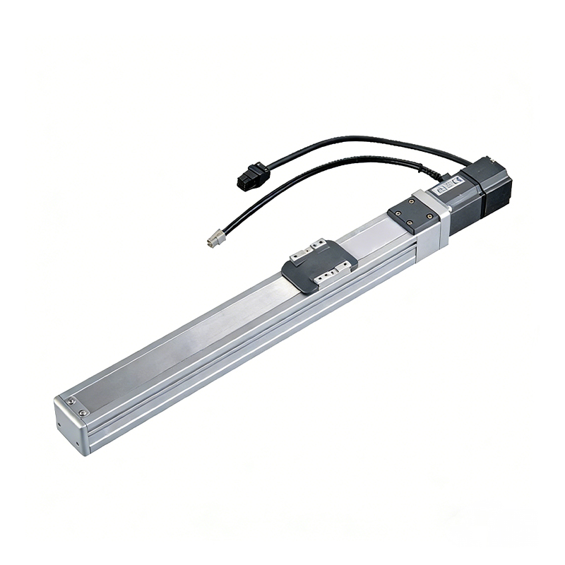 0.01mm High Precision Light Load Ball Screw Linear Module
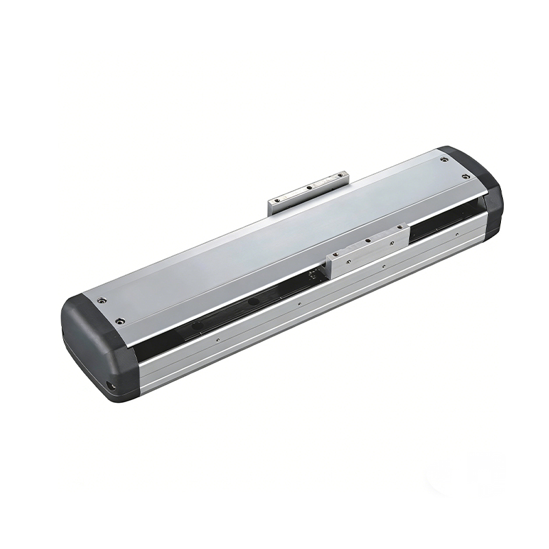 Ball Screw Linear Module with Built-in Sensor
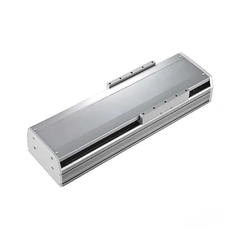 2000mm Long Stroke Ball Screw Linear Module
This 2000mm Long Stroke Ball Screw Linear Module is customized for large-range linear movement automation tasks, support...
READ MOREThis 2000mm Long Stroke Ball Screw Linear Module is customized for large-range linear movement automation tasks, support...
READ MOREThis 2000mm Long Stroke Ball Screw Linear Module is customized for large-range linear movement automation tasks, support...
READ MOREThis 2000mm Long Stroke Ball Screw Linear Module is customized for large-range linear movement automation tasks, support...
READ MORE
If you are interested in our products, please leave us a message. We look forward to providing you with
professional services!
Innovation and transcendence make factory intelligent manufacturing efficient and convenient!
+86 186 2508 0683
19962977901
sales@sz-tys.com
Building 5, Suzhou Mudu International Science and Technology Innovation Park, Jinfeng South Road, Suzhou City, Jiangsu Province, China
