


 English
 Français
 русский
 عربى
عربى Español
 Deutsch
Tel
+86 186 2508 0683

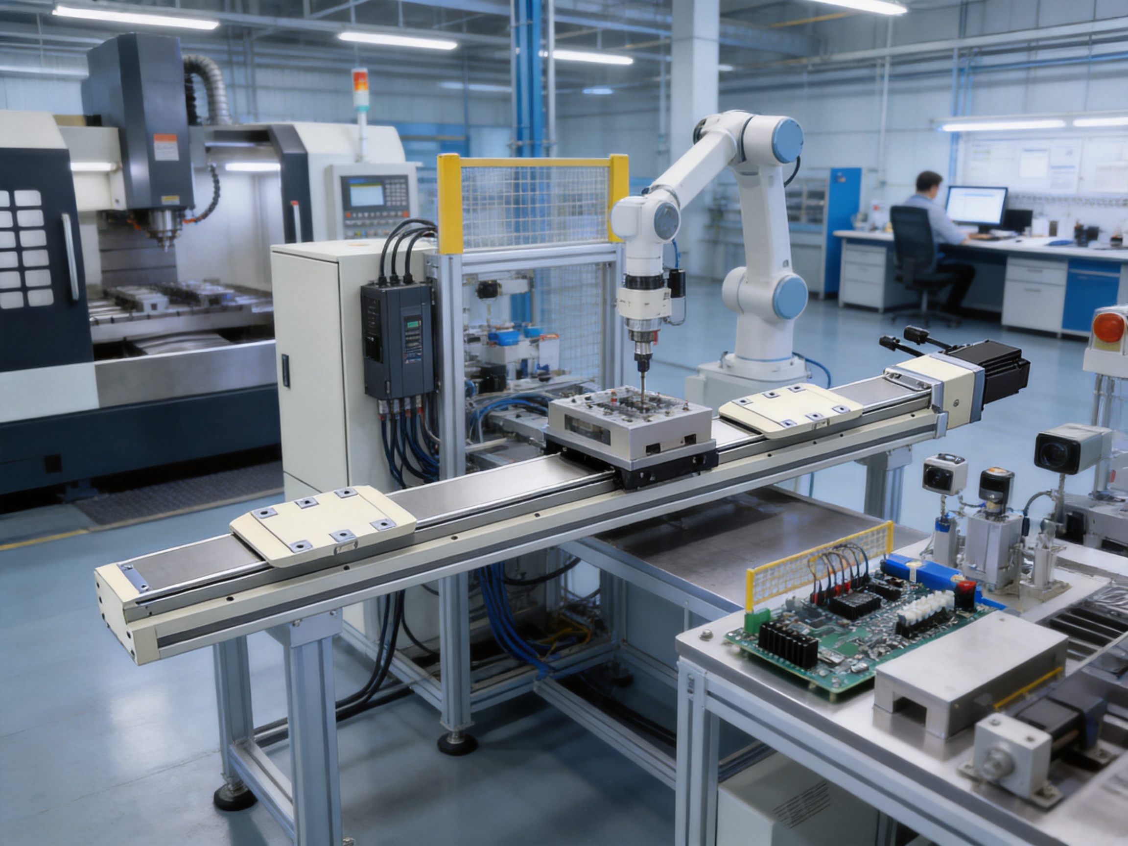
Precision automation increasingly depends on motion systems that can combine high positioning accuracy, stable load handling, dependable service life, and flexible integration. A linear module is no longer judged only by its nominal travel distance or maximum speed. Engineers must also consider how evenly a load is supported, how the carriage behaves under offset forces, how easily the module can be installed, which motor and drive combinations are available, and whether the product can maintain performance over extended production cycles.
The Dual-Slider High Precision Rail-Embedded Linear Module is designed for applications that require controlled linear motion together with improved load distribution. Its defining feature is a two-slider configuration integrated with high-precision guide rails and a ball-screw transmission system. Compared with a conventional single-slider module, the dual-slider architecture provides a broader support arrangement, helping improve movement stability and load-bearing uniformity when the payload is distributed across two carriages.
This configuration makes the module suitable for multi-point positioning, parallel handling, precision alignment, electronic manufacturing, precision instrument assembly, automated inspection, and other applications in which smooth and repeatable movement is essential. With a repeatability specification of ±0.01 mm, a maximum speed of 250 mm/s, a rated thrust of 1,388 N, and available strokes from 25 mm to 450 mm in 25 mm increments, the module offers a practical balance between precision, force capacity, compact integration, and configuration flexibility.
The product is manufactured and supplied by Suzhou Tongyousheng Electronic Technology Co., Ltd., a high-tech automation enterprise engaged in the research, development, production, and sales of electric cylinders, linear motion modules, linear motor modules, servo presses, robotic seventh axes, and multi-degree-of-freedom motion platforms. Its experience across several motion-control product categories supports the development of integrated solutions for intelligent manufacturing and Industry 4.0 applications.
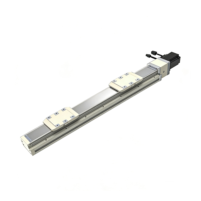
Dual-Slider High Precision Rail-Embedded Linear Module
The Dual-Slider High Precision Rail-Embedded Linear Module is a mechanically guided linear motion unit. Its main body contains a precision guide system and a ball screw that converts rotary motor movement into controlled linear displacement. The drive motor is coupled to the ball screw, while the two sliding blocks travel along the embedded rail structure.
The two sliders may be used as a coordinated pair or configured for specific application requirements. In a synchronized arrangement, both sliders support the same working platform or handling fixture, helping distribute the applied load and reduce uneven support. In applications requiring separate working positions, the dual-slider arrangement can also support multi-point operation or specialized tooling layouts, subject to the selected control and mechanical configuration.
The rail-embedded construction provides a protected and integrated motion structure. Instead of requiring a separate external guide arrangement for many standard applications, the guide rail and transmission components are combined into a compact module body. This can simplify machine design, reduce the number of components that must be aligned during assembly, and help manufacturers achieve a cleaner automation layout.
The module is available with motor placement options including motor right side, motor left side, motor exposed, and motor bottom side. These configurations allow designers to adapt the motor location to surrounding equipment, cable routing, available installation space, and the preferred orientation of the machine.
Typical applications include loading and unloading mechanisms, transfer units, precision positioning stations, inspection platforms, packaging machinery, electronic component handling, assembly fixtures, dispensing systems, and automated testing equipment. The product can also serve as one axis in a multi-axis Cartesian system or as part of a more complex robotic and intelligent manufacturing line.
The following table summarizes the principal specifications provided for the module. Actual performance depends on installation orientation, payload distribution, acceleration, duty cycle, environmental conditions, motor selection, and control settings.
| Specification | Value | Engineering Significance |
| Module category | Rail-Embedded Linear Module | Integrated guide and transmission structure for compact linear motion |
| Slider configuration | Dual slider | Improved support distribution and movement stability compared with a single-slider arrangement |
| Repeatability | ±0.01 mm | Suitable for repeatable positioning and alignment operations |
| Ball screw lead | 5 mm | Supports controlled movement and useful thrust capability |
| Maximum speed | 250 mm/s | Suitable for moderate-speed transfer and positioning cycles |
| Maximum horizontal payload | 50 kg with dual carriage | Supports substantial loads when installed horizontally and correctly configured |
| Maximum vertical payload | 15 kg with dual carriage | Vertical operation requires consideration of gravity, braking, and motor selection |
| Rated thrust | 1,388 N | Provides useful linear force for handling and positioning applications |
| Available stroke | 25–450 mm | Available at 25 mm intervals |
| Ball screw | C7, diameter 16 mm | Precision transmission component for linear motion |
| Servo motor output | 400 W | Available motor configuration for the stated standard arrangement |
| Coupling size | 10 × 14 mm | Mechanical interface information for motor and screw connection |
| Home sensor | EE-SX674, NPN; FC-SPX307Z-2M, NPN | External home-position sensing options |
| Design service life | 10,000 km under normal catalog conditions | Indicative service-life value when used within specifications |
The maximum payload figures should not be interpreted as universal values for every installation. Horizontal and vertical capacities are affected by the center of gravity, overhang distance, acceleration and deceleration, installation stiffness, operating frequency, and the direction of applied forces. Engineers should evaluate the complete load case rather than selecting a module solely from the nominal payload number.
The most important advantage of this product is the use of two sliding blocks. A single-slider module may be adequate for centered loads with limited overhang, but an offset workpiece or long fixture can create uneven forces and moments. The dual-slider layout increases the support span and distributes the working load over two points.
This arrangement can reduce localized loading on the guide system and help the moving platform remain more stable during acceleration, deceleration, and direction changes. It is especially useful when the workpiece is wide, when a tooling plate extends beyond the centerline, or when several components must be carried on one moving axis.
Offset loads generate moments around the guide and transmission system. The product provides specified static loading moments of 318 N·m for MY, 318 N·m for MP, and 626 N·m for MR. These values provide reference points for evaluating pitch, yaw, and roll-related loading conditions.
Although the values must be checked against the actual application, the dual-slider structure offers an inherent mechanical advantage over a narrow single-support arrangement. A broader carriage support can help reduce angular movement and maintain a more consistent tool position when the center of gravity is not directly above the guide center.
The two sliders can be used for synchronized movement or for application-specific positioning arrangements. Synchronized movement is valuable when both sliders carry one rigid platform, such as a gripper plate, inspection fixture, or transfer frame. The arrangement helps keep the platform supported at multiple points as it moves along the axis.
For more specialized systems, dual-slider modules can support multiple tooling positions or separate process points. The exact independent-operation capability depends on the mechanical version, drive configuration, control architecture, and application design. These details should be confirmed during technical selection, but the dual-slider format provides more design possibilities than a basic single-carriage module.
The stated repeatability of ±0.01 mm makes the module suitable for operations that require consistent return to a programmed position. Examples include component alignment, inspection positioning, insertion assistance, dispensing, electronic assembly, and test-station movement.
Repeatability is not the same as absolute accuracy. Actual positioning performance is influenced by screw accuracy, assembly quality, servo tuning, temperature, structural rigidity, sensor arrangement, and the mechanical relationship between the payload and the moving carriage. Even so, the repeatability specification indicates that the module is intended for more demanding applications than general-purpose low-precision transport equipment.
The 5 mm ball screw lead represents a practical design choice for controlled linear motion. A smaller lead generally supports greater mechanical advantage and more precise displacement per motor revolution, while a larger lead may favor higher linear speed. With a maximum speed of 250 mm/s and a rated thrust of 1,388 N, this configuration is suitable for many positioning, transfer, and moderate pressing-related tasks.
The correct operating point depends on the selected motor, drive, payload, acceleration profile, and duty cycle. Applications requiring rapid long-distance travel may require a different transmission arrangement, while applications requiring greater force or very high acceleration should be evaluated through a detailed sizing calculation.
Product comparisons should be based on the complete application rather than on one isolated specification. A single-slider module may be lighter, less expensive, or sufficient for a centered payload. However, when the application includes a long fixture, a wide workpiece, an offset center of gravity, or repeated changes in acceleration, the dual-slider product can provide important advantages.
| Evaluation Factor | Conventional Single-Slider Module | Dual-Slider High Precision Rail-Embedded Module |
| Load support | Load is concentrated through one primary carriage | Load is distributed through two sliding blocks |
| Resistance to offset loads | May require strict center-of-gravity control | Better suited to wider or offset tooling when correctly sized |
| Platform stability | Can be more sensitive to pitch and yaw moments | Broader support arrangement improves stability |
| Application flexibility | Generally optimized for one carriage position | Supports synchronized or application-specific dual-slider layouts |
| Horizontal payload capability | Depends on the individual model and carriage | Up to 50 kg with dual carriage under stated conditions |
| Integration | May require additional support or external guide components | Integrated rail and transmission structure simplifies many machine layouts |
| Precision positioning | Varies by guide and transmission design | Specified repeatability of ±0.01 mm |
| Best suited applications | Centered, compact, lower-moment loads | Precision transfer, multi-point positioning, alignment, and distributed loads |
The comparison does not mean that a dual-slider module is automatically superior for every machine. Adding a second slider can increase mechanical complexity and product weight. The advantage becomes most valuable when the application benefits from greater support, better moment handling, and more stable movement. A professional selection process should compare total system performance, not only purchase price or component count.
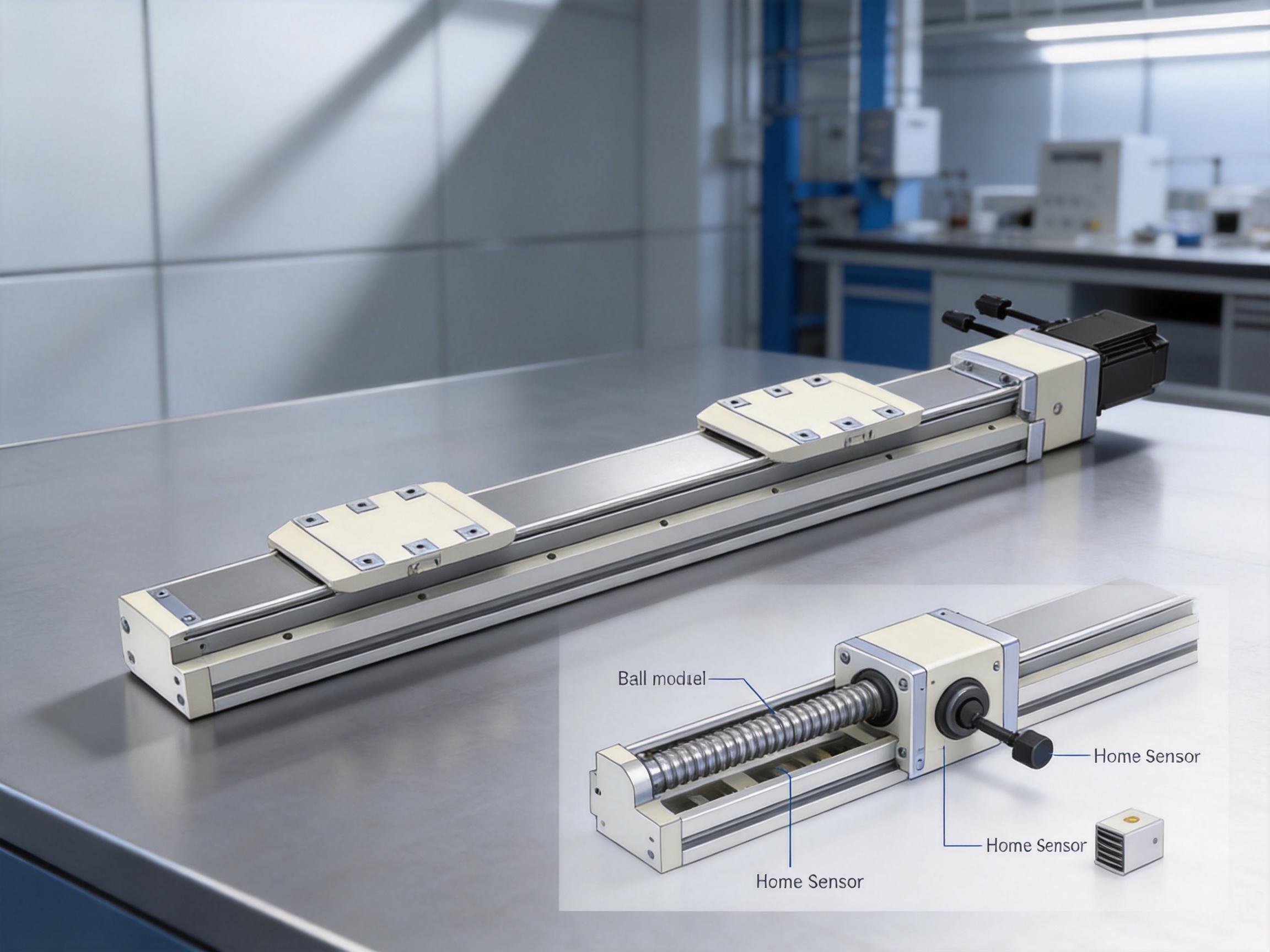
The module combines high-precision guide rails with a ball screw transmission. The guide system controls the path of the moving sliders, while the ball screw transfers motor torque into linear movement. Separating these functional roles allows the module to provide controlled travel while supporting external loads and moments through the rail structure.
The stated ball screw is a C7, 16 mm diameter component. The C7 designation is commonly associated with a defined grade of screw travel accuracy, although the final positioning performance of the assembled module also depends on preload, machining, assembly, thermal behavior, servo control, and the accuracy of the reference system. The specification should therefore be considered together with the ±0.01 mm repeatability rating and the requirements of the machine process.
Precision machining is particularly important for the body, guide mounting surfaces, screw supports, carriage interfaces, and motor coupling alignment. Small errors in parallelism or concentricity can increase friction, produce uneven motion, and reduce service life. The manufacturing approach used for a high-quality module must therefore include controlled machining, careful assembly, inspection, and functional testing.
Suzhou Tongyousheng Electronic Technology Co., Ltd. reports that it operates with advanced design software, high-precision CNC machining centers, an experienced research and development team, and a portfolio of core patents. These capabilities support the production of components with controlled dimensional relationships and enable the company to develop customized motion solutions for different automation environments.
A linear module is a system rather than a collection of unrelated parts. The guide rail, ball screw, motor, coupling, sensors, body, mounting holes, and control interface must work together. A manufacturer with experience across electric cylinders, servo presses, linear motor modules, and motion platforms can approach product development from both mechanical and system perspectives.
Tongyousheng’s product portfolio includes electric cylinders, linear motion modules, linear motor modules, servo press machines, robotic seventh axes, and six-degree-of-freedom platforms. This breadth can support cross-disciplinary engineering knowledge in force control, trajectory planning, structural design, sensing, and motion coordination.
The company also describes cooperation with state-owned enterprises, defense technology institutions, and leading universities. Such cooperation can strengthen the connection between practical industrial requirements, technical research, and product development. For customers with specialized requirements, this background may be useful when standard catalog configurations need to be adapted to a particular machine architecture.
High-precision CNC machining centers are essential for producing straight, stable, and repeatable module bodies. The quality of the mounting surfaces directly affects guide alignment and the smoothness of slider travel. Accurate machining also supports consistent hole patterns, repeatable assembly, and reliable installation by the customer.
For a dual-slider module, machining quality is especially important because the two sliders must remain properly aligned with one another. Any significant deviation can cause binding, uneven load sharing, increased drive torque, or premature wear. The body and guide interfaces must therefore be manufactured and assembled with attention to parallelism, flatness, perpendicularity, and screw alignment.
The module includes dimensional information for horizontal, wall-mounted, vertical, and motor-location configurations. Offering several mounting orientations helps equipment builders adapt the axis to different layouts. A horizontal axis may be used for transfer, a wall-mounted axis for side access, and a vertical axis for lifting or lowering a tooling fixture.
Each orientation changes the loading conditions. A horizontal installation may permit a payload of up to 50 kg under the stated dual-carriage conditions, while the vertical payload specification is 15 kg. Vertical applications must also account for gravity, holding torque, brake selection, emergency-stop behavior, and the consequences of power loss.
The module is listed with 400 W motor options and compatibility information for Mitsubishi, Panasonic, and Delta systems. The specified examples include motor and driver combinations for horizontal and vertical applications, with brake-equipped motors identified for vertical use.
| Brand | Application | Motor Model | Driver Model | Brake |
| Mitsubishi | Horizontal | HG-KN43J-S100 | MR-JE-40A | No brake |
| Mitsubishi | Vertical | HG-KN43BJ-S100 | MR-JE-40A | Brake equipped |
| Panasonic | Horizontal | MHMF042L1U2M | MBDLN25SE | No brake |
| Panasonic | Vertical | MHMF042L1V2M | MBDLN25SE | Brake equipped |
| Delta | Horizontal | ECM-B3M-C20604RS1 | ASD-B3-0421-L | No brake |
| Delta | Vertical | ECM-B3M-C20604SS1 | ASD-B3-0421-L | Brake equipped |
The source material identifies this group as options of stepper motors, although the listed motor and drive model families are servo products. For procurement and engineering documentation, the motor classification should be confirmed with the supplier before ordering. The available information clearly indicates that Mitsubishi, Panasonic, and Delta motor-drive packages are offered for different mounting and braking requirements.
Motor selection should consider not only nominal output. Engineers should verify continuous torque, peak torque, reflected inertia, acceleration, deceleration, vertical holding requirements, thermal conditions, duty cycle, encoder compatibility, and emergency-stop performance. A brake is particularly important for many vertical axes, but a brake should not be treated as the only safety measure. A complete risk assessment and suitable mechanical or control safeguards remain necessary.
The module is available in stroke lengths from 25 mm to 450 mm at 25 mm intervals. This range covers short-stroke alignment tasks as well as longer transfer operations. Standardized increments make product selection easier and can reduce the need for completely custom mechanical designs.
For the motor-right, motor-left, and motor-bottom-side configurations, the listed body length L starts at approximately 514.5 mm for a 25 mm stroke and increases with stroke length. For a 450 mm stroke, the listed length is approximately 1,364.5 mm. The motor-exposed configuration has slightly different dimensions, beginning at approximately 528 mm for a 25 mm stroke and reaching approximately 1,378 mm for a 450 mm stroke.
The body dimension tables also include mounting-related values identified as A, M, N, and P, together with product weight. The exact values vary according to stroke and motor arrangement. These dimensions should be used during machine layout and verified against the latest engineering drawing before fabrication.
A specific mounting note applies to the 50 mm stroke version. The top-locking mounting holes on the main body may be blocked by the slider, allowing only four screws to be used for fixation. The recommended solution is to secure the main body through the bottom-locking mounting holes. This detail demonstrates why mechanical installation should be reviewed from the beginning of the machine design process rather than after the module has been selected.
Weight also changes with stroke and motor configuration. Longer modules naturally require additional structural material and transmission length. The product tables provide kilogram values for each listed stroke. Equipment designers should include the mass of the module itself when calculating the payload of another axis or the total load on a robot, gantry, or support frame.
Payload capacity alone does not fully describe a linear axis. A relatively light fixture may create a high moment if its center of gravity is far from the slider or if the load is positioned above, below, or to the side of the guide. The product documentation provides allowable overhang reference data for horizontal, wall-mounted, and vertical installations.
| Installation | Payload Reference | Allowable Dimension A | Allowable Dimension B | Allowable Dimension C |
| Horizontal | 20 kg | 1,560 | 153 | 237 |
| Horizontal | 35 kg | 890 | 81 | 126 |
| Horizontal | 50 kg | 550 | 53 | 82 |
| Wall-mounted | 20 kg | 214 | 153 | 1,435 |
| Wall-mounted | 35 kg | 113 | 81 | 845 |
| Wall-mounted | 50 kg | 74 | 53 | 506 |
| Vertical | 10 kg | 331 | 331 | Not specified |
| Vertical | 15 kg | 220 | 220 | Not specified |
The table should be read together with the original mechanical drawing because the meaning of each dimension depends on the referenced installation diagram. Values are not universal overhang allowances for every load shape. If the center of gravity is high or offset, the resulting moment may exceed the guide capacity even when the total payload is below the nominal limit.
The listed static moments are MY 318 N·m, MP 318 N·m, and MR 626 N·m. These figures describe reference moment capacities around the product’s principal axes. Engineers should compare the calculated application moments with the appropriate values and include suitable safety margins. Dynamic forces caused by acceleration, deceleration, impact, vibration, or sudden stops must also be considered.
Electronic manufacturing often requires repeatable movement between feeders, assembly locations, cameras, testing fixtures, and discharge positions. The ±0.01 mm repeatability specification and dual-slider support can benefit applications in which a fixture must return to a consistent location without excessive vibration or platform deflection.
The module may be used for printed circuit board handling, component transfer, alignment before inspection, connector insertion assistance, camera positioning, and movement between multiple processing points. The final suitability depends on cleanroom requirements, dust control, payload geometry, cycle time, and the accuracy required by the process.
Precision instrument production commonly involves small but high-value components, delicate housings, optical parts, sensors, and calibrated mechanisms. Smooth movement is important because sudden vibration or excessive carriage play can affect assembly quality. A dual-slider platform can help support fixtures that are wider than the moving screw centerline or that require stable multi-point support.
The module can serve as a positioning axis for screwdriving, adhesive dispensing, component alignment, inspection, and transfer operations. Its compact integrated design can also help equipment builders create modular stations with fewer separate guide components.
Testing systems often move a product into a defined measurement position and then return it to a loading or unloading area. Repeatability, stable support, and predictable sensor referencing are essential in these systems. The external home-sensor options allow the machine designer to establish a repeatable reference position for initialization and recovery procedures.
For test fixtures with multiple contact points, the two sliders can provide a more stable base than a single narrow carriage. This may help maintain fixture alignment when probes, connectors, or measurement heads apply forces to the product under test.
Parallel handling applications often require a long or wide gripper plate to remain level while moving. The dual-slider design can support both ends of a platform and help reduce twisting during movement. This is useful for trays, panels, electronic assemblies, and multiple-part fixtures.
Multi-point positioning is another suitable use. A single axis can move a fixture through several defined process stations, while the dual carriage arrangement supports the mechanical platform. When separate movement of the sliders is required, the control system and mechanical design must be specified accordingly.
The module can be integrated into Cartesian robots, gantry systems, transfer lines, and robotic auxiliary axes. Its stroke range and motor-location options support different machine layouts, while the 400 W motor configurations provide a starting point for standard automation designs.
When used as a seventh axis or auxiliary linear axis, the module’s own mass and payload must be included in the robot or support-system calculation. The installation structure should be sufficiently rigid to prevent vibration and maintain the positioning performance of the module.
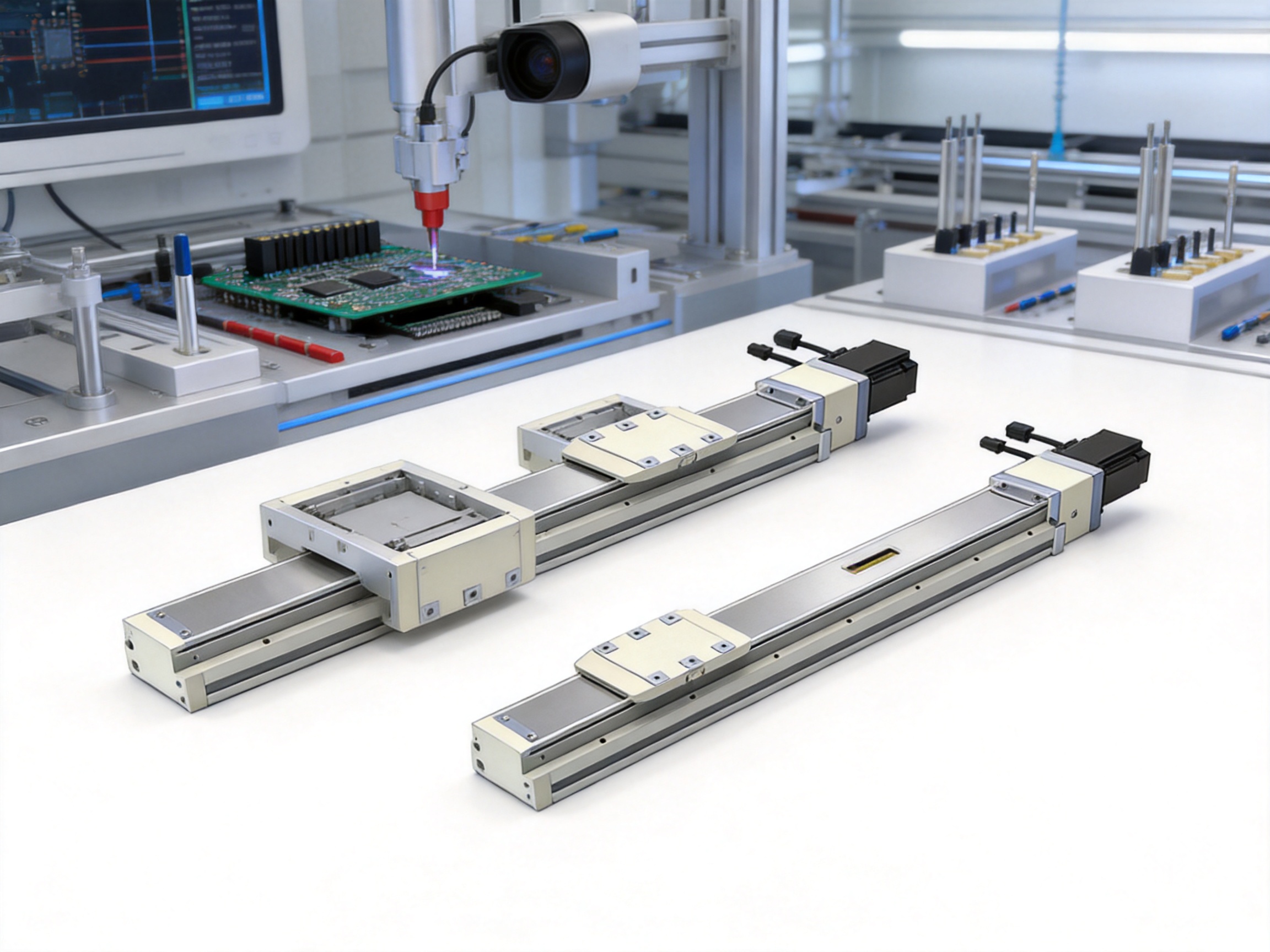
Proper installation is essential for realizing the advantages of a precision dual-slider module. The mounting surface should be clean, rigid, and sufficiently flat. Uneven support can distort the module body and increase friction, resulting in uneven travel or higher motor load.
The installer should verify that all mounting holes are accessible for the selected stroke and motor configuration. The 50 mm stroke mounting limitation should receive particular attention. Where the top-locking holes are obstructed, the bottom-locking holes should be used as recommended.
The module should be aligned with the connected machine structure before tightening all fasteners. External components should not force the sliders into an offset position. A workpiece platform should be mounted so that its load is distributed as evenly as practical across the two sliders.
Cable routing should allow the full stroke without pulling on the motor, sensor, or connectors. Cables should be supported to prevent repeated bending at a sharp radius. Sensors should be positioned and tested before automatic operation begins.
For vertical installation, the selected motor should include the required brake configuration where appropriate. The system should be tested for controlled stopping, power-loss behavior, emergency-stop response, and prevention of unintended downward movement. The standard specifications do not apply to ceiling-mounted inverted use, so customers requiring an inverted arrangement should obtain specific technical guidance before proceeding.
Commissioning should begin at low speed and low acceleration. The technician should verify the direction of travel, home sensor operation, limit behavior, end-of-stroke clearance, and communication between the motor drive and machine controller. Initial movement should be performed without the final payload whenever possible.
After basic movement has been confirmed, the load can be introduced gradually. The technician should monitor motor current, vibration, noise, temperature, position error, and repeatability. Abnormal resistance may indicate misalignment, excessive preload, an installation problem, or a payload moment beyond the allowable range.
Servo tuning should be completed with the actual mechanical load or a representative test load. Excessive gain can cause vibration, while insufficient gain can produce following error or sluggish response. Acceleration and deceleration should be selected according to payload, screw speed, mechanical stiffness, and required cycle time.
The home sensor should be used as part of a repeatable initialization procedure. If the application requires high absolute accuracy, the machine may also require additional calibration, external measurement, or process-specific compensation. The module’s repeatability rating provides a useful foundation, but the complete machine accuracy depends on every element in the motion chain.
The stated guaranteed service life is 10,000 km when the product is used normally and in compliance with the specifications in the catalog. Service life is affected by payload, speed, acceleration, moment loading, lubrication, contamination, installation quality, and operating environment.
Routine maintenance should include inspection of the guide and screw area, confirmation of mounting fastener tightness, review of cable condition, verification of sensor operation, and observation of unusual sound or vibration. Lubrication should follow the manufacturer’s instructions and should be suitable for the operating environment.
Contamination control is important in precision motion systems. Dust, metal particles, liquids, and process residues can enter moving interfaces or affect the ball screw and guide surfaces. Where the application generates contaminants, the machine designer should consider covers, shields, extraction, suitable sealing, and a defined cleaning schedule.
Excessive overhang and moment loading should be avoided even if the total mass appears acceptable. A fixture that is too long or mounted too far from the slider can accelerate guide wear and reduce repeatability. Load calculations should be repeated when tooling, product size, process force, or operating speed changes.
The principal competitive advantage of the product is not one isolated specification but the combination of several useful characteristics. The dual-slider configuration supports more stable load handling, the embedded rail structure promotes compact integration, the ball screw provides controlled thrust, and the range of stroke and motor arrangements gives machine builders practical design flexibility.
Compared with a lower-cost single-slider alternative, the product can reduce the need for additional external support in applications with wide fixtures or offset payloads. It can also provide a more stable foundation for precision alignment and multi-point handling. In a complete machine, reducing separate guide components may simplify assembly and reduce alignment work.
Compared with a basic belt-driven axis, the ball-screw transmission may be preferable where repeatability, thrust, and controlled positioning are more important than very high long-distance speed. The maximum speed of 250 mm/s is suited to many compact automation cycles, while the rated thrust of 1,388 N supports handling and positioning tasks that may exceed the practical capability of lightweight belt systems.
Compared with a fully custom linear axis, the standardized stroke increments, motor options, sensor choices, and dimensional tables can shorten the engineering process. Customers can begin with a proven catalog configuration and then discuss modifications if the application requires a special interface, motor, sensor, or installation arrangement.
The manufacturer’s broader automation portfolio is another strength. A supplier that develops electric cylinders, servo presses, linear modules, motion platforms, and robotic axes can support customers whose projects eventually expand from one linear axis into a complete motion system. This can make technical communication more consistent across mechanical, electrical, and control requirements.
Not every application can be solved with a standard module. Customers may require a nonstandard stroke, special mounting pattern, customized carriage plate, different motor brand, alternative sensor position, modified cable outlet, protective cover, or integration with a particular controller.
The manufacturer’s research and development capability, CNC machining resources, design software, and experience with automation equipment provide a foundation for customization. A project discussion should include the required travel, payload, center of gravity, installation orientation, cycle time, acceleration, precision, environmental conditions, motor and drive preference, and safety requirements.
For vertical or high-inertia applications, customers should provide detailed load information rather than relying only on the nominal payload value. The supplier can then evaluate thrust, torque, brake requirements, screw speed, guide loading, static moments, and expected service life.
Customization should be controlled through engineering drawings and approval procedures. Changes to stroke, mounting, motor position, or carriage design can affect body length, weight, cable routing, and load capacity. A formal review helps ensure that the customized product remains suitable for the intended machine.
When selecting the Dual-Slider High Precision Rail-Embedded Linear Module, first identify the required stroke. Standard options range from 25 mm to 450 mm at 25 mm intervals. Select the shortest stroke that provides the required working range plus appropriate clearance.
Next, calculate the total moving load, including the workpiece, fixture, cables, gripper, tooling plate, and any process force. Determine the center of gravity in relation to the sliders and calculate the resulting moments.
Confirm the installation orientation. Horizontal, wall-mounted, vertical, and inverted arrangements impose different loading and safety conditions. Inverted ceiling-mounted use is not covered by the standard specifications and requires technical confirmation.
Choose the motor and drive combination according to payload, acceleration, speed, duty cycle, and control requirements. For vertical applications, evaluate brake requirements and power-loss behavior.
Check available installation space using the correct motor-location drawing. Verify overall length, mounting-hole access, cable clearance, product weight, and the relationship between the moving platform and surrounding components.
Confirm sensor requirements and controller compatibility. The listed home sensors are NPN types, so the machine input circuit must be compatible with the selected sensor arrangement.
Finally, review environmental conditions, maintenance access, lubrication requirements, required service life, and safety measures. A complete selection process reduces the risk of performance problems during commissioning.
The product uses two sliding blocks instead of one. This helps distribute the load across a wider support arrangement, improves stability, and makes the module better suited to wide fixtures, offset loads, parallel handling, and applications involving greater moment loading.
The stated repeatability is ±0.01 mm. Actual system performance depends on installation, motor tuning, load conditions, temperature, sensor referencing, and the accuracy requirements of the complete machine.
The listed maximum speed is 250 mm/s. The appropriate operating speed may be lower depending on payload, acceleration, screw speed, duty cycle, vibration limits, and required service life.
The listed maximum horizontal payload is 50 kg with dual carriage, while the listed maximum vertical payload is 15 kg with dual carriage. These values must be evaluated together with overhang, center of gravity, moment loading, acceleration, and installation orientation.
Stroke options range from 25 mm to 450 mm in 25 mm increments. Overall module length varies according to stroke and motor-location configuration.
The provided configuration data lists Mitsubishi, Panasonic, and Delta motor and driver combinations. The listed motor output is 400 W. Customers should confirm the final motor classification, model, brake option, connector, and drive compatibility before ordering.
A brake-equipped motor is identified for the listed vertical configurations. Vertical systems must also include appropriate control, mechanical support, emergency-stop, and power-loss measures. The brake selection should be confirmed through an application-specific review.
The product description states that the dual-slider design allows synchronous or independent operation for various automation tasks. The precise independent-operation method depends on the selected mechanical and control configuration and should be confirmed with the supplier.
The standard specifications do not apply to ceiling-mounted inverted use. Customers requiring this arrangement should contact the manufacturer for a dedicated technical evaluation.
For the 50 mm stroke version, the top-locking mounting holes may be blocked by the slider, allowing only four screws to be used for fixation. The recommended installation method is to use the bottom-locking mounting holes.
The guaranteed service life is 10,000 km when the module is used normally and within the catalog specifications. Actual life depends on loading, lubrication, contamination, speed, acceleration, installation quality, and maintenance.
The module provides linear motion through a ball screw and can be used in positioning and force-related automation systems. However, applications requiring controlled pressing force, force monitoring, or high-cycle pressing should be evaluated as complete servo press systems rather than selected solely from the module’s positioning specifications.
The Dual-Slider High Precision Rail-Embedded Linear Module is a strong choice for automation systems that require stable, repeatable, and flexible linear motion. Its two-slider design addresses an important limitation of conventional single-carriage systems by distributing loads more effectively and improving resistance to offset forces and moments.
The combination of a high-precision guide rail, C7 16 mm ball screw, 5 mm lead, 1,388 N rated thrust, ±0.01 mm repeatability, 250 mm/s maximum speed, and stroke options from 25 mm to 450 mm gives equipment builders a practical platform for electronic manufacturing, precision assembly, automated testing, parallel handling, and multi-point positioning.
Its competitive value is strengthened by multiple motor locations, available Mitsubishi, Panasonic, and Delta configurations, external NPN home sensors, detailed overhang references, and a broad automation product portfolio from the manufacturer. The company’s R&D team, high-precision CNC machining centers, design resources, patent portfolio, and experience with integrated motion systems support both standard product delivery and application-specific development.
For the best result, engineers should size the module according to the complete mechanical load case, including payload, center of gravity, overhang, dynamic forces, installation orientation, and required duty cycle. When correctly selected, installed, and maintained, this dual-slider rail-embedded module can provide a dependable foundation for precision motion and intelligent manufacturing equipment.
1. Product specification materials for the Dual-Slider High Precision Rail-Embedded Linear Module, including performance, dimensional, sensor, motor, and installation data.
2. Internal product structure and stroke-dimension tables for motor-right, motor-left, motor-exposed, and motor-bottom-side configurations.
3. Manufacturer information concerning research and development, CNC machining, automation equipment, patents, and Industry 4.0 solutions.
4. General engineering principles for ball-screw linear motion systems, guide loading, static moments, payload calculation, and servo motor selection.
5. General industrial practices for linear actuator installation, lubrication, commissioning, safety evaluation, and preventive maintenance.
6. Motor and drive selection data for Mitsubishi, Panasonic, and Delta configurations supplied with the product information.
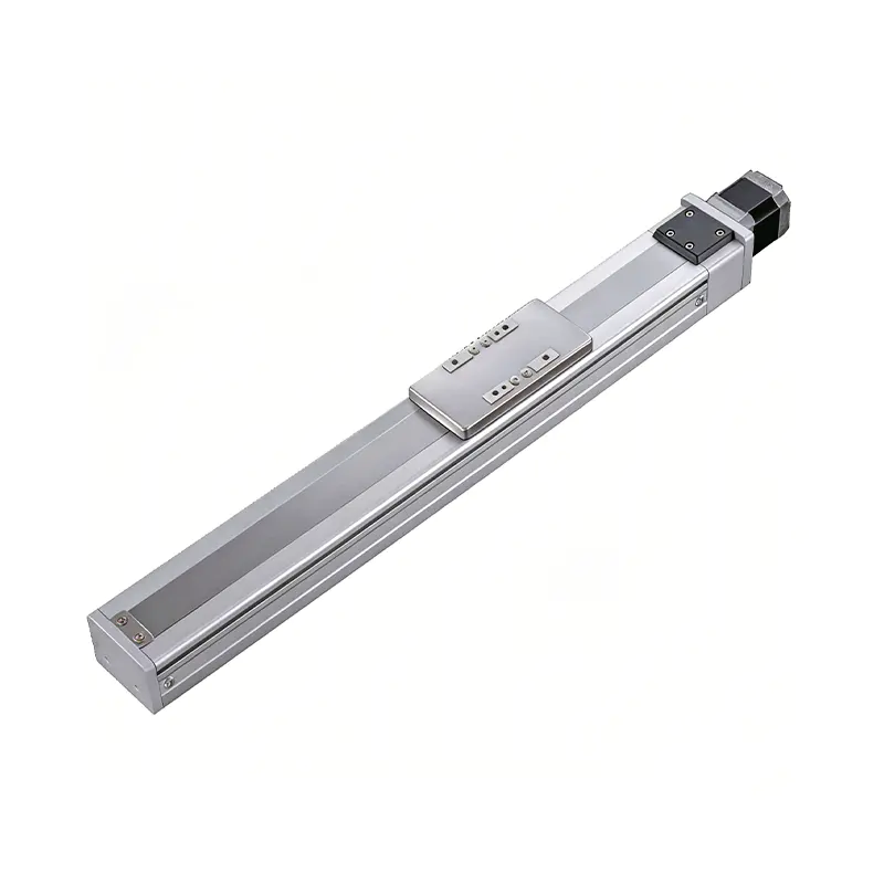 0.01mm High Precision Ball Screw Driven Rail-Embedded Linear Module
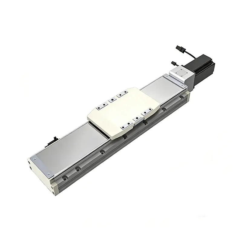 Heavy Load Ball Screw Driven Rail-Embedded Linear Module
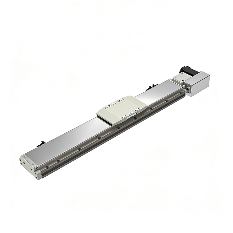 110KG Load Long Stroke Rail-Embedded Linear Module
Dual-Slider High Precision Rail-Embedded Linear Module
110KG Load Long Stroke Rail-Embedded Linear Module
Dual-Slider High Precision Rail-Embedded Linear Module
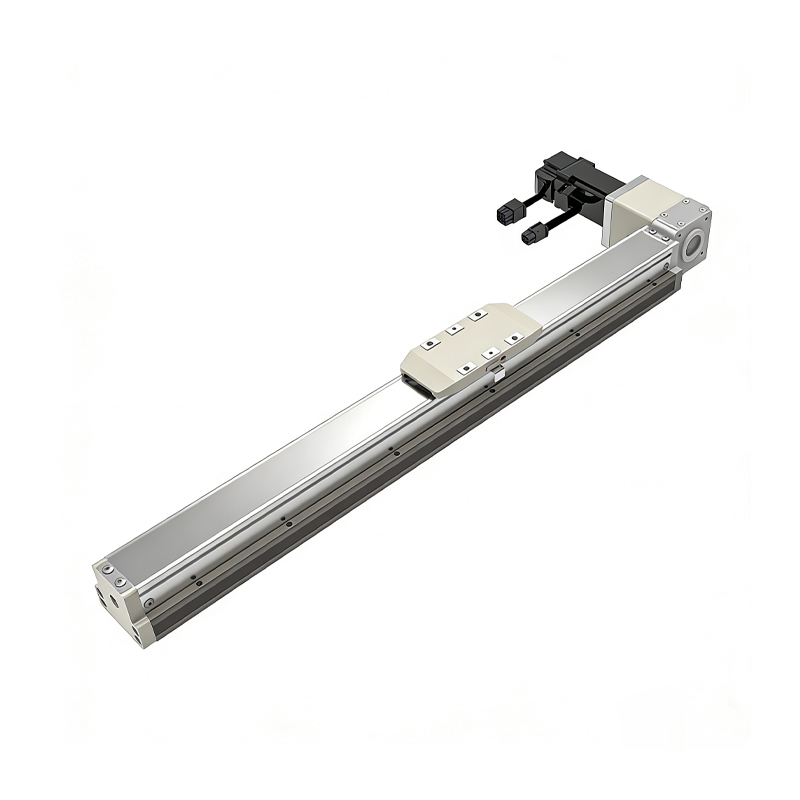 Belt Driven Dust-Proof Rail-Embedded Linear Module
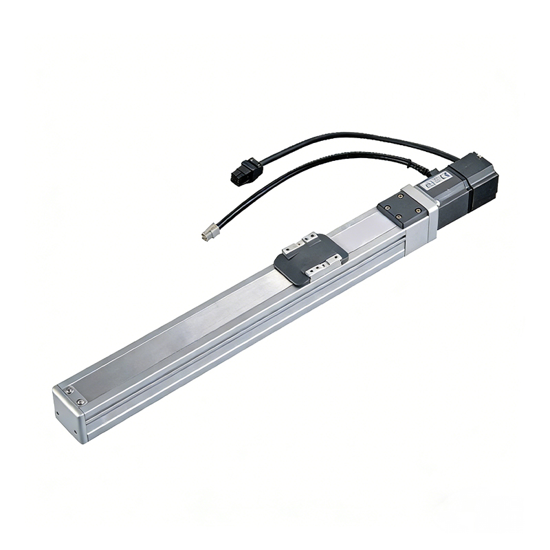 0.01mm High Precision Light Load Ball Screw Linear Module
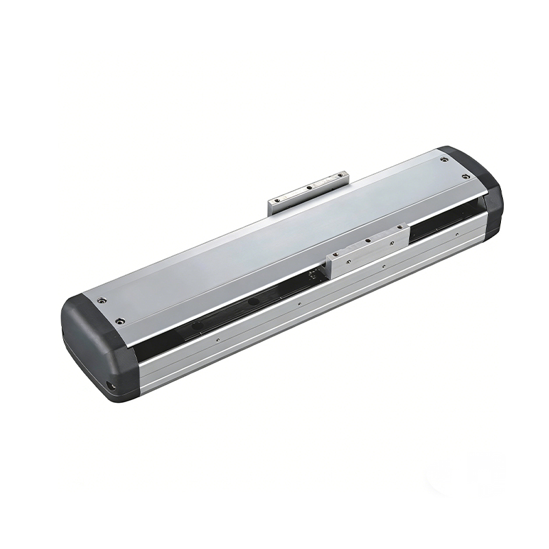 Ball Screw Linear Module with Built-in Sensor
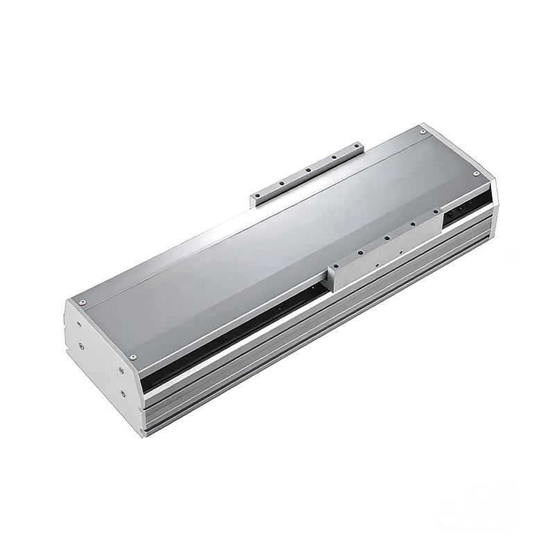 2000mm Long Stroke Ball Screw Linear Module
This 2000mm Long Stroke Ball Screw Linear Module is customized for large-range linear movement automation tasks, support...
READ MOREThis 2000mm Long Stroke Ball Screw Linear Module is customized for large-range linear movement automation tasks, support...
READ MOREThis 2000mm Long Stroke Ball Screw Linear Module is customized for large-range linear movement automation tasks, support...
READ MOREThis 2000mm Long Stroke Ball Screw Linear Module is customized for large-range linear movement automation tasks, support...
READ MORE
If you are interested in our products, please leave us a message. We look forward to providing you with
professional services!
Innovation and transcendence make factory intelligent manufacturing efficient and convenient!
+86 186 2508 0683
19962977901
sales@sz-tys.com
Building 5, Suzhou Mudu International Science and Technology Innovation Park, Jinfeng South Road, Suzhou City, Jiangsu Province, China
