


 English
 Français
 русский
 عربى
عربى Español
 Deutsch
Tel
+86 186 2508 0683

Modern automation systems increasingly require motion components that combine long travel, high acceleration, precise positioning, reliable load handling, and straightforward integration. In many production environments, a linear axis must move products, tools, fixtures, or robotic payloads across a considerable distance while maintaining stable performance over thousands of operating cycles. Conventional mechanical transmission systems can perform these tasks, but they may introduce backlash, friction, wear, lubrication requirements, acoustic noise, or limitations in speed and acceleration. The TYSM11-L medium linear motor module addresses these challenges with a direct-drive linear motor architecture designed for demanding industrial motion applications.
With a body width of only 115 mm, the module provides a maximum stroke of 3,720 mm, a maximum speed of 2,000 mm/s, continuous thrust of 203 N, and acceleration up to 2 G. It can support a maximum load of 45 kg under the stated operating condition of 0.5 m/s and 0.5 G. These specifications position the TYSM11-L between compact, lightweight linear stages and larger heavy-duty transfer systems. It is intended for users who need a long axis without accepting excessive installation width, low dynamic response, or complicated mechanical maintenance.
The module is suitable for material transfer, assembly automation, inspection equipment, packaging lines, industrial positioning, robotic auxiliary axes, machine tending, and other applications where rapid and repeatable linear movement is essential. Its surface-mounted dual-rail configuration supports stable guidance, while the linear motor eliminates the mechanical screw or belt transmission typically found in conventional electric linear modules. The result is a clean, responsive, and adaptable motion platform for modern intelligent manufacturing systems.
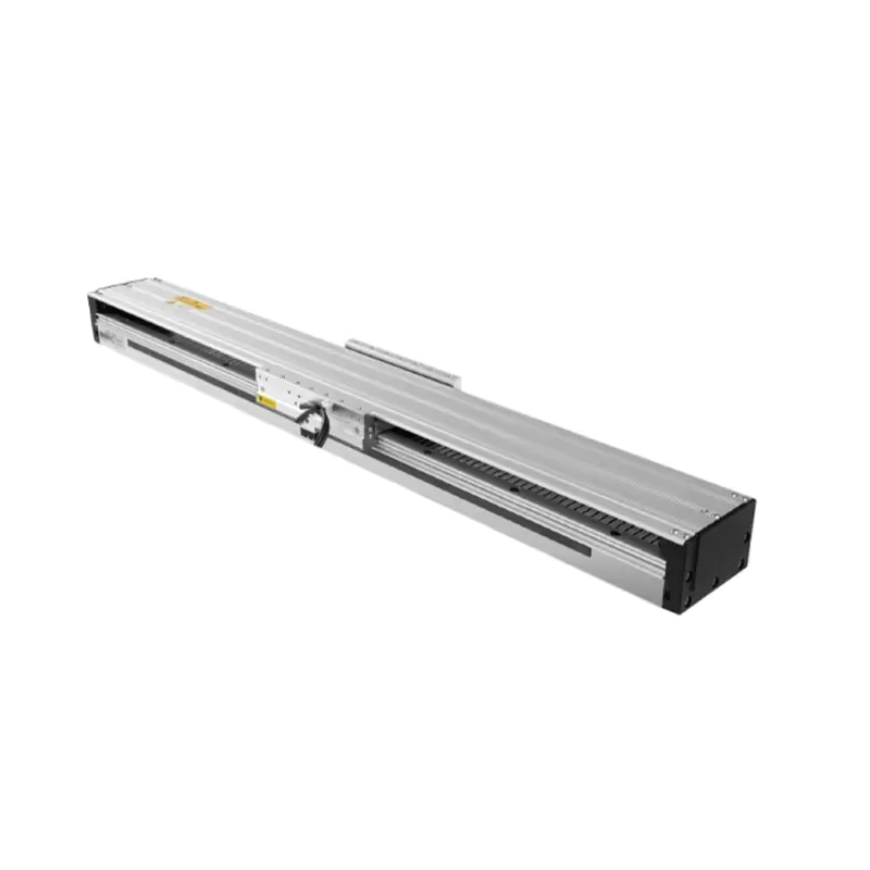
Long-Travel High-Thrust Medium Linear Motor Module
The TYSM11-L is a medium linear motor module designed around the principle of direct linear propulsion. Instead of converting rotary motor motion through a ball screw, timing belt, rack-and-pinion arrangement, or other mechanical transmission, a linear motor produces force directly along the travel axis. This construction reduces the number of moving transmission elements and allows the motion controller to command acceleration, velocity, and position with a highly responsive drive system.
The module consists of a long structural body, a linear motor drive arrangement, a moving carriage, and a surface-mounted dual rail guidance system. The carriage is supported by the two rails while the motor generates the thrust required for movement. The guidance and propulsion functions are therefore coordinated within a compact industrial unit. Depending on the machine layout, the module can be mounted horizontally or on a wall. The product information also includes load and moment data for different operating orientations and dynamic conditions, helping engineers evaluate payload capability during machine design.
Unlike a conventional rotary motor and screw assembly, a direct-drive linear motor has no screw nut, belt, gearbox, or rack that must continuously transmit motion through physical contact. This can reduce mechanical compliance and transmission losses. It also allows the axis to accelerate quickly because the system does not need to repeatedly speed up a long rotating screw or move a belt through pulleys. For applications involving frequent starts, stops, indexing operations, or rapid reciprocating movement, these characteristics can improve cycle-time performance.
The product is classified as a medium linear motor module because it balances structural capacity and compactness. It is not intended merely for miniature laboratory positioning, nor is it an oversized transport rail. Its 115 mm body width provides a practical compromise between installation space and mechanical stability. This makes it suitable for equipment builders who require a relatively long axis but cannot accommodate a very wide structural frame.
The principal specifications of the TYSM11-L are summarized below. Actual performance depends on payload distribution, mounting orientation, acceleration profile, duty cycle, environmental conditions, controller settings, and the mechanical installation. Engineers should therefore use the values as design references and confirm the final configuration with the supplier during system development.
| Specification | Value | Engineering Significance |
|---|---|---|
| Product model | TYSM11-L | Medium linear motor module for long-travel applications |
| Body width | 115 mm | Compact installation envelope for a medium-capacity axis |
| Maximum speed | 2,000 mm/s | Supports rapid transfer and high-throughput operation |
| Continuous thrust | 203 N | Provides sustained propulsive force for industrial movement |
| Maximum stroke | 3,720 mm | Enables long-distance travel within one integrated module |
| Maximum acceleration | 2 G | Allows fast response and reduced positioning cycle time |
| Maximum load | 45 kg at 0.5 m/s and 0.5 G | Suitable for medium payload transfer under specified conditions |
| Guidance system | Surface-mounted dual rail | Improves carriage support, stability, and repeatability |
| Guaranteed service life | 10,000 km under normal compliant use | Provides a useful reference for lifecycle planning |
One of the most important features is the relationship between stroke and overall module length. The configuration data lists multiple lengths from approximately 340 mm to 3,996 mm, with corresponding changes in module weight. This allows equipment designers to select a length that matches the required working envelope rather than purchasing an oversized axis. The available configuration range supports both compact installations and extended travel applications.
The maximum speed of 2,000 mm/s is particularly valuable in transfer systems. A high-speed axis can reduce the time required to move components between processing stations, especially when the travel path is long. However, speed should always be considered together with acceleration, deceleration distance, payload, vibration, and settling time. The practical cycle time is not determined by top speed alone. A well-tuned profile that reaches a suitable speed without excessive vibration may provide better productivity than a nominally faster profile that requires a long settling period.
The continuous thrust rating of 203 N indicates the motor’s ability to provide sustained force during normal operation. Peak thrust, duty cycle, and thermal conditions may differ from continuous performance and should be checked for applications involving repeated high-force acceleration. The stated 45 kg maximum load is provided at a defined speed and acceleration condition, which emphasizes the importance of application-specific selection. Payload capability decreases as acceleration increases because more force is required to accelerate the load. Orientation also affects the available capacity because vertical or wall-mounted motion may impose additional gravitational and structural demands.
A direct linear motor produces movement without requiring a rotary-to-linear conversion mechanism. In a ball screw axis, a motor rotates a screw and a nut converts that rotation into linear travel. In a belt axis, the motor rotates a pulley and the belt transfers force to the carriage. Each additional transmission element contributes inertia, friction, compliance, tolerance accumulation, and possible wear. The TYSM11-L removes much of this mechanical chain, enabling a more direct connection between command input and carriage movement.
Direct drive can improve dynamic responsiveness because the motor force acts immediately on the moving element. This is beneficial for applications requiring rapid acceleration, short positioning cycles, and repeated changes of direction. It can also reduce backlash-related errors because there is no screw nut or gear mesh that must reverse through mechanical clearance. Although the overall system still depends on feedback resolution, structural rigidity, bearing quality, servo tuning, and installation accuracy, the direct-drive architecture creates a strong foundation for precise positioning.
Long-travel ball screws may experience critical-speed limitations, deflection, vibration, or the need for rotating support structures. Timing belts can provide long travel, but their elasticity, tension variation, and transmission compliance may affect positioning performance. Rack-and-pinion systems can cover substantial distances but require careful adjustment of gear engagement and may introduce backlash or noise. A linear motor module avoids the need to rotate a long screw and does not depend on a belt loop or gear rack to transfer motion across the entire travel range.
The 3,720 mm maximum stroke and 2,000 mm/s maximum speed make the TYSM11-L well suited to extended transfer paths. This is useful in production lines where several stations are arranged along one axis. A single module can move a fixture, gripper, inspection head, or workpiece carrier between stations while maintaining a compact mechanical footprint. Consolidating the travel mechanism into one engineered module can also simplify machine architecture and reduce the time required for alignment during assembly.
The module supports acceleration up to 2 G. High acceleration does not mean that every payload should be operated at the maximum value, but it gives the machine designer additional performance headroom. A system can be configured with a lower acceleration for fragile products, a moderate value for general transfer, or a higher value for empty-carriage movement and short-cycle applications.
High acceleration is valuable when the required travel distance is moderate and the machine must complete many repeated movements per hour. It reduces the time spent in acceleration and deceleration zones, allowing the axis to spend more of the cycle at productive motion or to complete short moves without needing to reach a low capped speed. For assembly and inspection equipment, this can increase throughput while maintaining consistent positioning behavior.
Traditional screw and belt systems require inspection and maintenance of their transmission elements. Ball screws may require lubrication and protection from contamination. Belts may require tension checks, replacement, and inspection for wear. Gear systems require lubrication and careful alignment. A linear motor module has fewer mechanical transmission components, which can reduce routine maintenance associated with torque transfer.
Reduced mechanical maintenance does not mean maintenance-free operation. The rails, carriage bearings, motor surfaces, cable management, sensors, mounting bolts, and protective covers still require appropriate inspection. Dust, metal particles, coolant, moisture, and impact can affect any precision motion system. However, removing a long mechanical screw or belt from the primary drive path can simplify the service plan and reduce the number of wear-sensitive parts.
The surface-mounted dual rail system provides support for the carriage and helps resist pitch, yaw, and roll loads generated by payload offset or acceleration. A single rail may be sufficient for lightweight equipment, but two rails offer a broader support base and improved load distribution. This is important when the payload is mounted above the carriage, extends away from the axis centerline, or experiences changing forces during rapid motion.
The module includes static loading moment values of 1,742 N·m for MY, 1,742 N·m for MP, and 2,951 N·m for MR, with the torque values referenced to the center of gravity. These figures help engineers evaluate whether a proposed payload and mounting arrangement are within the module’s structural limits. Since moment is affected by both force and offset distance, a payload with a moderate mass may create a substantial moment if its center of gravity is positioned far from the carriage.
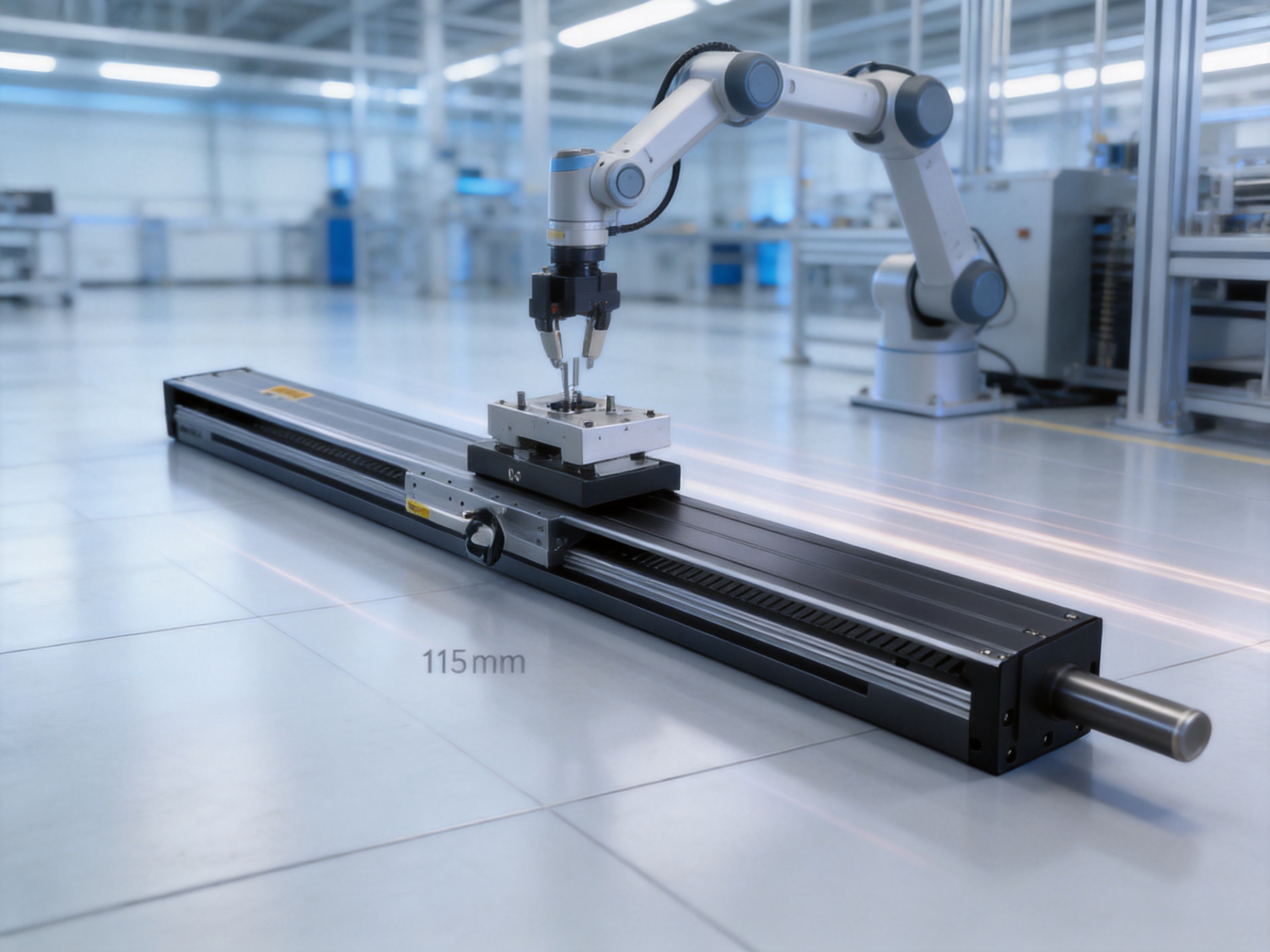
Load selection is one of the most important stages in linear module design. The payload is not limited only by its mass. The engineer must consider the center of gravity, mounting surface, acceleration, deceleration, travel direction, vibration, external process forces, cable drag, and the required service life. The TYSM11-L provides load data for horizontal and wall-mounted installation at several combinations of speed and acceleration.
For horizontal installation at 0.5 m/s and 5 m/s² acceleration, the listed load examples include 30 kg, 35 kg, and 45 kg, with corresponding application dimensions identified in the product data. At 0.8 m/s and 8 m/s², the listed loads include 25 kg, 30 kg, and 40 kg. At 1 m/s and 10 m/s², the listed values include 23 kg, 28 kg, and 33 kg. At 1.5 m/s and 15 m/s², the examples include 12 kg, 15 kg, and 17 kg. At 2 m/s and 20 m/s², the examples include 9 kg, 10 kg, and 11 kg.
These figures demonstrate a basic engineering principle: allowable load decreases as speed and acceleration increase. The motor must generate force to overcome the inertia of the payload, and the guide system must withstand the resulting dynamic loads. A machine designer should not select the 45 kg value simply because it is the largest number in the specification. Instead, the load should be matched to the actual motion profile and the required safety margin.
Wall-mounted installation has different load examples. At 0.5 m/s and 5 m/s², the listed values include 20 kg, 25 kg, and 28 kg. At 0.8 m/s and 8 m/s², the examples include 12 kg, 20 kg, and 23 kg. At 1 m/s and 10 m/s², the listed loads include 10 kg, 15 kg, and 20 kg. At 1.5 m/s and 15 m/s², the examples include 9 kg, 11 kg, and 13 kg. At 2 m/s and 20 m/s², the listed values include 7 kg, 9 kg, and 11 kg.
Ceiling-mounted inverted operation is not covered by the standard specifications. If an application requires inverted installation, the supplier should be consulted for confirmation of allowable loads, bearing orientation, protection, cable routing, safety retention, and service-life implications. This qualification is important because mounting orientation can affect both structural loading and the consequences of a power interruption.
A payload should be mounted as close as practical to the carriage’s intended load center. A tall or offset payload can create a moment that is much greater than the force associated with its mass alone. During acceleration and deceleration, this moment can lead to deflection, vibration, uneven bearing loading, or reduced service life. The dual-rail design provides a stable foundation, but it cannot eliminate the effects of poor load distribution.
Equipment designers should define the payload center of gravity in three dimensions and compare the resulting forces and moments with the module’s permitted values. Any tooling, gripper, sensor bracket, cable carrier, or product fixture should be included in the calculation. The design should also account for external process forces, such as pressing, inserting, cutting, dispensing, or inspection contact. Static and dynamic loads should be evaluated separately before a final selection is made.
A high-speed axis may still require a controlled deceleration phase and a final settling interval before a process begins. In precision assembly or inspection, the settling time can influence the total cycle more than the travel speed. A suitable motion profile should therefore balance acceleration, jerk, maximum speed, deceleration, and position tolerance.
The TYSM11-L gives users flexibility to optimize these parameters. For a long transfer with a heavy payload, the controller may use moderate acceleration and a higher cruising speed. For short indexing movements with a lighter payload, the system may use higher acceleration and a lower top speed. This flexibility is one of the advantages of a servo-controlled direct-drive axis compared with a fixed-speed mechanical transfer mechanism.
The product data provides a broad range of body lengths and corresponding module weights. The listed lengths begin at approximately 340 mm and continue through configurations near 3,996 mm. The module weight increases progressively with length, from about 9 kg for a short configuration to approximately 54.8 kg for one of the longest listed configurations.
| Representative Module Length | Approximate Module Weight | Typical Design Consideration |
|---|---|---|
| 340 mm | 9 kg | Compact equipment and short positioning paths |
| 700 mm | 13.5 kg | Medium-range transfer and indexing |
| 1,000 mm | 17.3 kg | General automation and station-to-station movement |
| 1,536 mm | 24 kg | Extended travel within a compact machine frame |
| 2,016 mm | 30 kg | Long material transfer and robotic auxiliary movement |
| 2,796 mm | 39.8 kg | Large work envelope and multi-station automation |
| 3,276 mm | 45.8 kg | Long production-line travel |
| 3,996 mm | 54.8 kg | Near-maximum configuration length |
The detailed configuration tables use K, N, L, and module weight values to identify different construction options. These codes are useful for matching a required travel length with the appropriate structural arrangement. Because the available combinations include repeated increments and different module lengths, the final order should be confirmed using the manufacturer’s model-selection documentation.
When selecting the module length, designers should distinguish between nominal body length, usable stroke, end-of-travel clearance, sensor space, cable routing space, and the length required for mounting brackets. A 3,720 mm working stroke may require a longer overall machine envelope than 3,720 mm because the module itself, protective components, moving cable loop, and safety clearance must be accommodated.
Long modules also require attention to support spacing and mounting flatness. The base should be sufficiently rigid to prevent bending or twisting. Uneven mounting surfaces can cause rail misalignment, increased friction, abnormal bearing load, or positioning errors. A carefully prepared mounting reference surface is therefore essential to achieving the expected performance of a long-travel linear motor module.
Ball screw modules are widely used because they can provide high thrust, good repeatability, and strong mechanical efficiency. They are often a sensible choice for short and medium strokes or applications requiring mechanical self-locking characteristics. However, a long screw can be limited by critical speed, whipping, deflection, and support requirements. Increasing screw length may also increase cost, installation complexity, and sensitivity to alignment.
The TYSM11-L offers a different performance profile. Its direct linear motor is particularly advantageous when long travel, high speed, frequent acceleration, and low mechanical transmission compliance are important. It avoids the need for a rotating screw extending across the entire axis. It may also reduce lubrication and screw-nut maintenance. On the other hand, a linear motor does not generally provide the same passive holding behavior as a mechanically locking screw, so vertical applications may require a brake, counterbalance, safety mechanism, or other protective measure.
Belt-driven modules are often economical and effective for long travel. They can move loads quickly and are relatively simple to construct. However, the belt is an elastic transmission element. Its tension, stiffness, wear, and temperature behavior can influence positioning repeatability. Belt systems may also require periodic tension adjustment and replacement.
The TYSM11-L can provide more direct force transmission and improved dynamic response than a belt-driven system. Its dual-rail support helps manage payload moments, and the absence of a long timing belt can reduce belt-related compliance. For high-cycle systems where repeatability and rapid response are more important than the lowest initial cost, a linear motor can offer a stronger long-term performance proposition.
Rack-and-pinion systems are useful for very long travel and can handle demanding industrial loads. They are commonly applied to gantries, robotic tracks, and large machine tools. Their performance depends on gear quality, backlash control, lubrication, rack alignment, and the ability to maintain consistent engagement along the full travel range.
The TYSM11-L is more compact and better suited to medium-load equipment where a complete rack-and-pinion assembly would be unnecessarily large. It provides an integrated linear motion unit with a 115 mm body width and a defined rail system. For applications requiring multiple acceleration and deceleration events, the direct-drive architecture can also reduce gear-related mechanical noise and clearance effects.
Some machines use rotary servomotors, gearboxes, and linkage mechanisms to create linear movement. These arrangements can be customized for special kinematics, but they introduce more components and may complicate calibration. A linear motor module offers a straightforward one-axis solution. It can be installed as a linear transport axis without designing a separate conversion mechanism.
This simplicity is particularly useful for modular machine construction. A standard motion controller can coordinate the linear motor axis with other servo axes, sensors, grippers, cameras, and programmable logic controllers. Equipment builders can therefore create reusable machine platforms with less mechanical redesign from one project to the next.
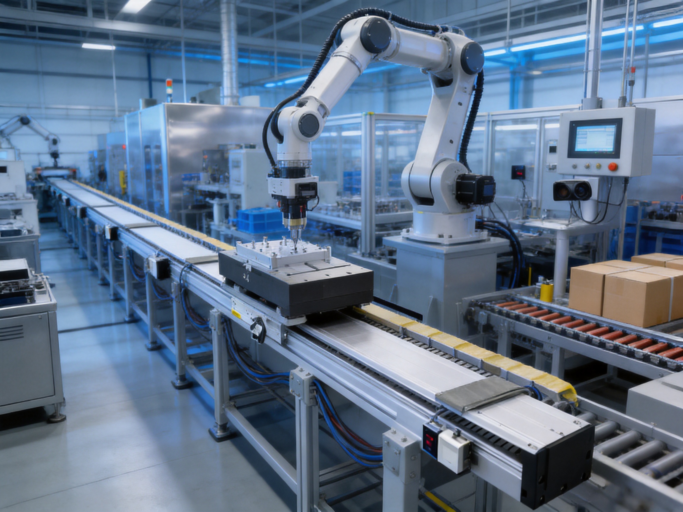
The long stroke and high speed make the TYSM11-L suitable for transferring components between multiple processing stations. A carriage can carry a fixture, tray, gripper, or product carrier along a common production route. This arrangement can reduce the number of separate short axes and simplify coordination between stations.
In a production line, the axis may move products from loading to assembly, inspection, labeling, testing, and unloading. The controller can use indexed positions, interpolation with other axes, or continuous motion depending on the process. The long travel capacity is useful when stations are distributed across a large working envelope.
Assembly systems often require quick movement between component feeders, assembly nests, and inspection points. The module can support a tool plate, gripper, or secondary actuator. Its high acceleration allows the system to reduce transfer time, while the dual-rail structure helps maintain tool stability during motion.
For processes involving insertion, fastening, dispensing, or pressing, the linear module can act as the transfer axis while a separate electric cylinder or servo press performs the process. This division of functions is valuable because the transfer axis can be optimized for speed and position, while the process actuator can be optimized for force and displacement control.
A long linear motor module can serve as an auxiliary axis for a robot. A robot mounted on the carriage can move along the production line, extending its reachable work envelope. Compared with a conventional belt or rack track, the direct-drive structure may provide fast repositioning and reduced mechanical compliance.
When used as a robotic axis, payload calculations must include the robot’s own mass, tooling, cables, workpiece, and the dynamic moments generated by robot motion. The high moment capacity listed for the module is helpful, but final verification should consider the robot’s changing center of gravity and the most demanding posture.
Inspection equipment may require a camera or sensor to scan a long product, a series of components, or multiple inspection zones. The TYSM11-L can position the inspection head rapidly and repeatably. Smooth servo motion can support image acquisition at defined positions or during controlled travel.
For vision applications, vibration management is essential. The module should be mounted on a rigid frame, and the motion profile should provide adequate settling time before image capture. The high speed capability can shorten repositioning time, while the controller can use lower acceleration during sensitive measurement phases.
Packaging machines often move cartons, trays, bottles, or pouches through loading and inspection processes. A long-travel axis can transfer products between conveyors or coordinate a pick-and-place system across several lanes. The ability to handle a medium payload while maintaining rapid motion makes the module appropriate for high-throughput packaging layouts.
Linear motion modules are also used in test rigs, motion simulators, laboratory automation, and special-purpose equipment. The TYSM11-L can provide a controlled linear degree of freedom for test fixtures or multi-axis platforms. Its compatibility with standard motion control architectures makes it suitable for systems that require synchronized movement with rotary or multi-axis mechanisms.
Suzhou Tongyousheng Electronic Technology Co., Ltd. is described as a high-tech enterprise integrating research and development, production, and sales. Its product range includes electric cylinders, linear motion modules, linear motor modules, servo presses, robotic seventh axes, and multi-degree-of-freedom motion platforms. This broad portfolio is significant because it indicates experience across several related areas of motion engineering rather than a focus on only one mechanical product.
The company maintains an experienced research and development team and uses advanced design software to develop motion products. Computer-aided mechanical design, structural analysis, motion simulation, and electrical system planning can help engineers evaluate a product before physical production. These tools are especially important for long-travel modules because rail alignment, structural deflection, carriage stiffness, cable routing, thermal behavior, and motor force must be considered together.
High-precision CNC machining centers support the production of accurately formed structural components and mounting surfaces. For a linear motor module, machining quality affects rail straightness, carriage smoothness, mounting repeatability, and the ability to maintain performance across a long stroke. Precision machining is therefore not merely an aesthetic or dimensional requirement; it directly influences motion stability and service life.
The company also reports a portfolio of core patents and cooperation with state-owned enterprises, defense technology institutions, and universities. Collaboration with research and industrial organizations can expose the engineering team to demanding requirements for reliability, control algorithms, structural design, and system integration. Such cooperation may also accelerate the transfer of research concepts into practical automation products.
Its manufacturing and development experience extends from linear modules and electric cylinders to servo presses, six-degree-of-freedom platforms, algorithmic control software, and multi-degree-of-freedom linkage systems. This cross-product expertise can benefit customers who need more than a standalone axis. A machine builder may require a linear motor module, electric actuator, servo press, and synchronized control system within the same project. A supplier with capabilities across these categories can support a more coordinated solution.
Quality, reputation, innovation, and development are identified as core company values. These principles are relevant to industrial automation because customers typically evaluate a motion component over its entire lifecycle, including selection, customization, delivery, commissioning, maintenance, and technical support. A product’s value depends not only on its catalog specifications but also on the supplier’s ability to provide engineering guidance and consistent manufacturing.
Design-to-production continuity is an important strength for customized automation components. When the same organization manages product development, manufacturing, and technical sales, feedback from application projects can be incorporated into future designs. It also helps reduce the risk that a design detail is lost during transfer between an external designer and a separate manufacturer.
For the TYSM11-L, this continuity can support the selection of body length, load arrangement, mounting orientation, motor configuration, sensor position, and control interface. It is particularly valuable when the customer’s application does not match a simple standard operating condition.
Long linear modules require more than a strong motor. The structural body, rail mounting, moving carriage, motor elements, end components, and cable system must work together consistently. CNC machining, controlled assembly procedures, inspection, and documented testing help maintain repeatability from one unit to the next.
For equipment manufacturers building multiple machines, product consistency is as important as peak performance. A standardized module with predictable dimensions and behavior can reduce machine commissioning time and simplify spare-part planning. It can also help a customer create a common platform for several equipment models.
The TYSM11-L is intended to integrate with standard motion control architectures. In a typical system, a servo drive controls the linear motor, a feedback device provides position information, and a programmable controller or motion controller generates the movement profile. Safety circuits, limit sensors, home sensors, and emergency-stop functions should be incorporated according to the machine’s risk assessment.
Control engineers should define the required position resolution, repeatability, velocity stability, acceleration profile, and settling behavior. The selected feedback system and drive must be compatible with the motor and the intended performance. Servo tuning should be performed after the module is installed on its final structure because the machine frame, payload, cable carrier, and tooling influence the dynamic response.
Long cable runs may require careful consideration of voltage drop, shielding, grounding, electromagnetic compatibility, and cable flex-life. The moving cable arrangement should be designed so that it does not impose excessive drag or side force on the carriage. A poorly routed cable chain can reduce motion quality even when the linear module itself is correctly installed.
For synchronized applications, the linear module can be coordinated with electric cylinders, servo presses, robotic axes, conveyors, or rotary tables. Electronic gearing, cam profiles, registration correction, and position-based triggering may be used depending on the process. This flexibility supports intelligent manufacturing systems in which motion, sensing, and production data are managed as one integrated operation.
The machine base should be rigid, level, and capable of maintaining alignment over the complete travel length. Mounting surfaces should be cleaned before installation, and fasteners should be tightened according to an appropriate sequence. If the module is installed on a long frame, the frame should be checked for twist and local deflection.
After installation, the carriage should be moved manually or at low speed, where appropriate, to confirm that there is no mechanical interference. Cable chains, sensors, end stops, and protective covers should be checked throughout the entire stroke. The payload should be mounted with the center of gravity positioned within the recommended region, and all external process forces should be included in the application assessment.
Initial commissioning should begin with low speed and low acceleration. The engineer can then verify sensor operation, travel limits, direction, feedback polarity, emergency-stop response, and position accuracy. Motion parameters should be increased gradually while observing vibration, noise, temperature, settling time, and current demand.
For long-travel operation, the full stroke should be tested rather than only the center section. End regions can reveal cable-routing issues, mounting irregularities, sensor interference, or structural deflection that may not appear during a short test. The final operating profile should include suitable acceleration and deceleration margins instead of relying continuously on the maximum catalog values.
The guaranteed service life is stated as 10,000 km when the product is used normally and in compliance with catalog specifications. This figure should be interpreted together with load, speed, acceleration, duty cycle, environmental conditions, mounting quality, and maintenance procedures. Exceeding the recommended moment or operating the module in an unsuitable orientation can reduce service life.
Routine maintenance should include inspection of the guide rails and carriage area, checking for contamination, verifying mounting fasteners, examining cable chains and flexible cables, and monitoring unusual noise or vibration. The linear motor surfaces and feedback components should be protected from metal debris, liquid contamination, and impact. The maintenance interval should be established based on operating hours, travel distance, environment, and criticality of the machine.
Condition monitoring can improve reliability. Servo current, following error, vibration, temperature, and cycle time may be tracked over time. A gradual increase in current or following error can indicate alignment changes, bearing wear, cable interference, or payload changes. Early detection allows maintenance to be scheduled before a failure interrupts production.
The TYSM11-L is a strong candidate when an application requires a combination of long travel, high speed, medium payload capacity, compact width, rapid acceleration, and direct-drive response. It is especially attractive when a belt system lacks stiffness, a ball screw becomes impractical at the required length, or a rack-and-pinion arrangement would be unnecessarily large.
Before ordering, the designer should prepare the following application information:
| Selection Item | Information to Confirm |
|---|---|
| Required travel | Usable stroke, end clearances, and total machine envelope |
| Payload | Mass of product, fixture, tooling, cables, and carriage-mounted equipment |
| Center of gravity | Three-dimensional location relative to the carriage mounting surface |
| Motion profile | Maximum speed, acceleration, jerk, cycle time, and duty cycle |
| Mounting orientation | Horizontal, wall-mounted, or a special arrangement requiring review |
| External force | Process forces from pressing, insertion, cutting, dispensing, or contact |
| Environment | Dust, liquid, temperature, cleanroom requirements, and contamination risk |
| Control system | Drive, feedback, communication, safety, and synchronization requirements |
| Service expectations | Travel distance, operating hours, maintenance access, and lifecycle target |
Applications with a high center of gravity, substantial offset tooling, frequent emergency stops, or large external process forces require additional engineering review. The supplier should be consulted for applications outside the published standard conditions, especially ceiling-mounted operation, unusual environmental exposure, high-temperature use, or special safety requirements.
The competitive value of the TYSM11-L comes from the combination of specifications rather than one isolated number. A 3,720 mm stroke, 2,000 mm/s speed, 203 N continuous thrust, 2 G acceleration, 45 kg stated maximum load, and 115 mm body width create a balanced product for medium-duty long-travel automation.
Some compact modules may offer a narrower body but lack the required stroke or payload capacity. Some heavy-duty axes may support a larger load but occupy more space and move more slowly. Some belt systems may provide long travel at a lower purchase price but require more attention to belt tension and compliance. Some ball screw systems may offer excellent thrust for shorter lengths but become less practical when the stroke increases. The TYSM11-L is designed for the area where these requirements overlap.
Its direct-drive architecture supports fast response, while the surface-mounted dual rails provide stable mechanical guidance. The available body lengths allow customers to select a practical configuration rather than adapting the machine around a fixed standard size. Its compatibility with standard motion control architectures also reduces the need for a proprietary control environment.
The supplier’s wider capabilities further enhance the product’s value. Customers can access related technologies such as electric cylinders, servo presses, multi-axis platforms, robotic axes, and control software. This can reduce integration complexity for projects that require several coordinated motion products. It also gives equipment builders a potential path from a single-axis prototype to a complete automation system.
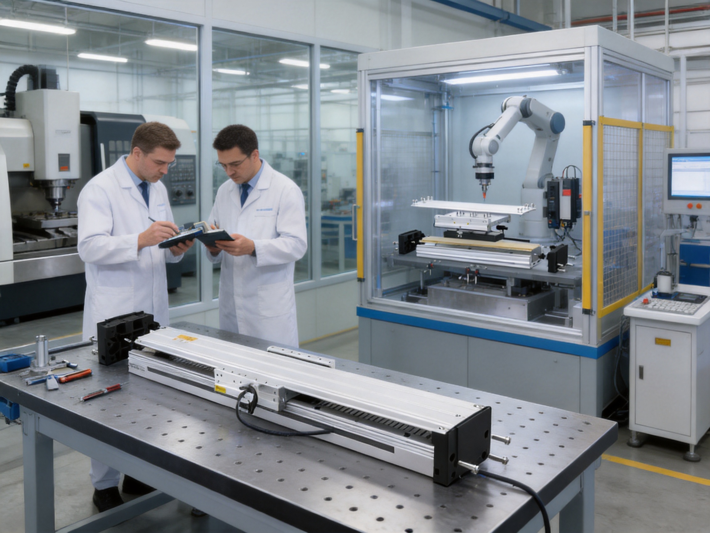
The TYSM11-L is designed for long-travel, medium-duty industrial automation. Typical applications include material transfer, assembly equipment, inspection systems, packaging machinery, robotic auxiliary axes, industrial positioning, and multi-station production lines.
The maximum stated stroke is 3,720 mm. The overall module length may be greater than the usable stroke because of end components, mounting requirements, sensor space, cable routing, and safety clearances.
The maximum speed is 2,000 mm/s. The appropriate operating speed depends on payload, acceleration, mounting orientation, vibration limits, settling time, and the required service life.
No. The 45 kg maximum load is specified at 0.5 m/s and 0.5 G. Allowable load decreases as speed and acceleration increase. The product data provides different load examples for several motion conditions, and the final application should be evaluated using the actual motion profile.
Wall-mounted installation is included in the product data with separate load examples. Vertical or other non-horizontal arrangements require consideration of gravitational force, payload retention, acceleration, and safety. Ceiling-mounted inverted use is not covered by the standard specifications and should be reviewed with the supplier.
A linear motor provides direct linear force without a rotating screw and nut. It can offer high speed, rapid acceleration, reduced backlash-related effects, lower mechanical transmission compliance, and less maintenance associated with screw lubrication and wear. A ball screw may still be preferable for certain high-thrust, short-stroke, or mechanically self-locking applications.
Yes. Although the direct-drive design removes many conventional transmission components, the rails, carriage, feedback components, cable system, mounting fasteners, and motor surfaces still require inspection and appropriate maintenance. Contamination and improper loading should be avoided.
The guaranteed service life is 10,000 km when the module is used normally and in accordance with the catalog specifications. Actual service life depends on load, speed, acceleration, mounting quality, environment, duty cycle, and maintenance.
The payload mass, center of gravity, offset distance, static and dynamic moments, external process forces, and cable drag should all be checked. The listed static moment values are 1,742 N·m for MY, 1,742 N·m for MP, and 2,951 N·m for MR, referenced to the center of gravity.
Yes. It is intended to work with standard motion control architectures and can be coordinated with electric cylinders, servo presses, robot axes, conveyors, rotary tables, sensors, and programmable controllers.
The supplier reports an experienced research and development team, advanced design software, high-precision CNC machining centers, core patents, and integrated research, production, and sales capabilities. Its product portfolio covers several motion technologies, supporting both individual components and broader automation solutions.
The customer should define the required usable stroke, end clearances, machine envelope, payload, speed, acceleration, mounting arrangement, and cable routing space. The available configuration data includes multiple lengths and weights. The final model should be confirmed with the supplier based on the complete application.
The TYSM11-L medium linear motor module is engineered for automation systems that require more than simple linear travel. Its combination of a 115 mm body width, 3,720 mm maximum stroke, 2,000 mm/s speed, 203 N continuous thrust, 2 G acceleration, and 45 kg stated maximum load provides a balanced solution for long-travel, medium-duty motion.
The direct-drive linear motor architecture provides fast response and avoids many limitations associated with long screws, belts, and gear transmissions. The surface-mounted dual-rail structure supports stable movement and helps manage payload moments. A wide range of length configurations allows the module to be adapted to compact machines, extended transfer systems, robotic tracks, and multi-station production lines.
Its performance should always be matched to the actual payload, center of gravity, acceleration, mounting orientation, duty cycle, environment, and control system. When correctly selected and installed, the module can help equipment builders improve throughput, simplify mechanical architecture, reduce transmission maintenance, and create flexible intelligent manufacturing systems.
Supported by integrated research and development, precision CNC manufacturing, application engineering, and a broader portfolio of automation products, Suzhou Tongyousheng Electronic Technology Co., Ltd. offers the TYSM11-L as part of a wider motion technology platform. For manufacturers seeking a compact but powerful long-travel axis, it represents a practical alternative to conventional mechanical transmission systems.
1. Product specification data for the TYSM11-L medium linear motor module, including speed, stroke, thrust, load, acceleration, moment, configuration, and service-life information.
2. Internal product overview and model configuration tables for long-travel linear motor modules.
3. General engineering principles for linear motor selection, payload calculation, acceleration profiling, and moment evaluation.
4. General design practices for industrial linear guides, servo motion systems, cable management, and machine commissioning.
5. Company information concerning research and development, CNC manufacturing, automation product development, and motion-control system integration.
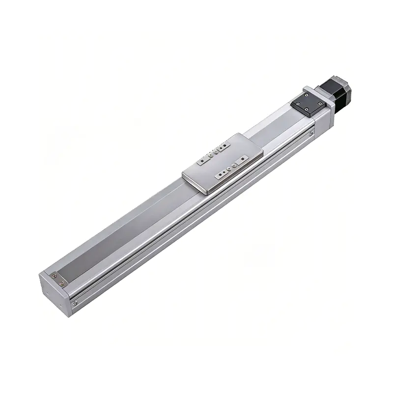 0.01mm High Precision Ball Screw Driven Rail-Embedded Linear Module
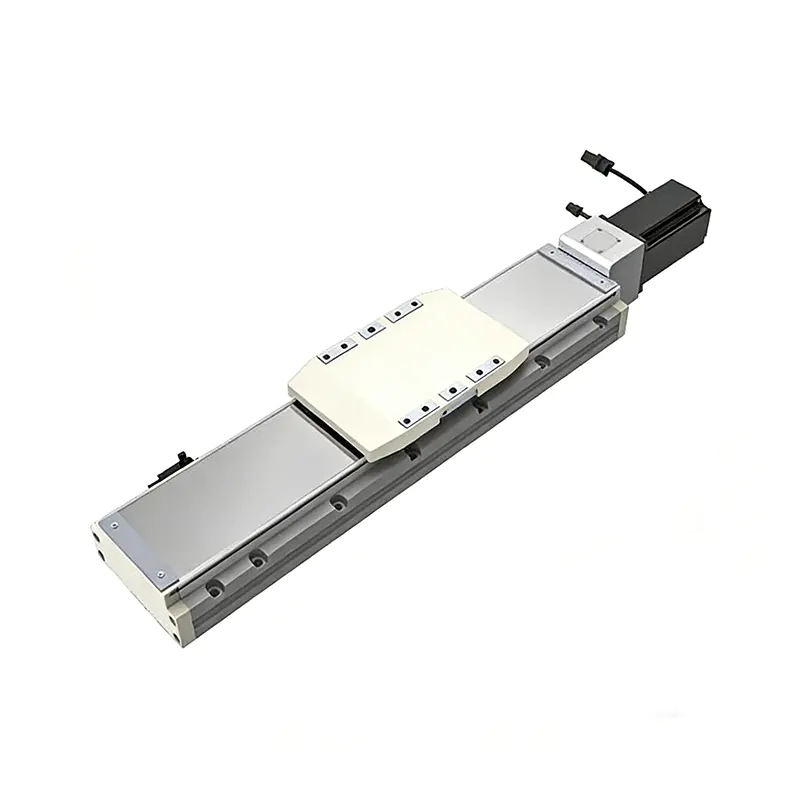 Heavy Load Ball Screw Driven Rail-Embedded Linear Module
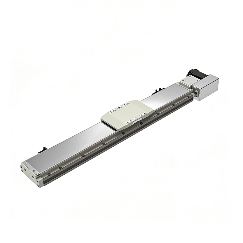 110KG Load Long Stroke Rail-Embedded Linear Module
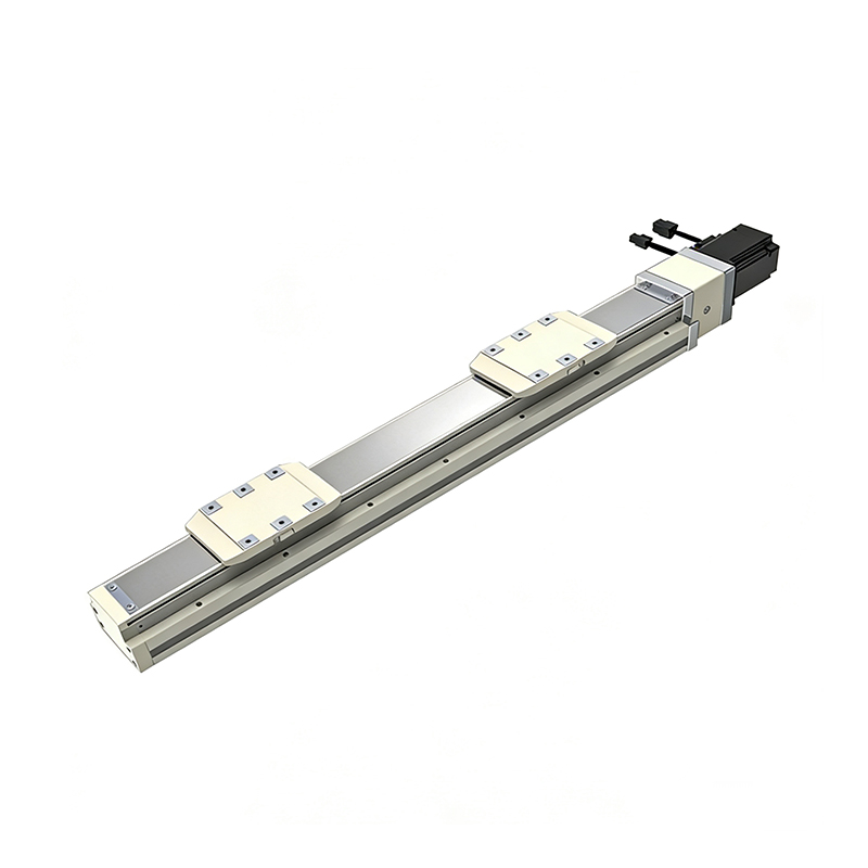 Dual-Slider High Precision Rail-Embedded Linear Module
 Belt Driven Dust-Proof Rail-Embedded Linear Module
 0.01mm High Precision Light Load Ball Screw Linear Module
 Ball Screw Linear Module with Built-in Sensor
 2000mm Long Stroke Ball Screw Linear Module
This 2000mm Long Stroke Ball Screw Linear Module is customized for large-range linear movement automation tasks, support...
READ MOREThis 2000mm Long Stroke Ball Screw Linear Module is customized for large-range linear movement automation tasks, support...
READ MOREThis 2000mm Long Stroke Ball Screw Linear Module is customized for large-range linear movement automation tasks, support...
READ MOREThis 2000mm Long Stroke Ball Screw Linear Module is customized for large-range linear movement automation tasks, support...
READ MORE
If you are interested in our products, please leave us a message. We look forward to providing you with
professional services!
Innovation and transcendence make factory intelligent manufacturing efficient and convenient!
+86 186 2508 0683
19962977901
sales@sz-tys.com
Building 5, Suzhou Mudu International Science and Technology Innovation Park, Jinfeng South Road, Suzhou City, Jiangsu Province, China
