


 English
 Français
 русский
 عربى
عربى Español
 Deutsch
Tel
+86 186 2508 0683

Modern manufacturing requires pressing equipment that can deliver repeatable force, accurate positioning, stable production rhythm, and complete process traceability. The Four Column C Frame Servo Press Machine is designed to meet these requirements in applications such as press-fit assembly, punching, riveting, powder compacting, sealing, spring testing, and electronic component processing. It combines the rigidity of a four-column support structure with the accessibility of a C-frame working area, creating a practical solution for manufacturers that need both structural stability and convenient part handling.
Unlike conventional mechanical presses that rely primarily on fixed stroke profiles, or hydraulic presses that may require more extensive maintenance and fluid management, a servo press can control force, position, speed, dwell time, and return movement through a programmable electric drive system. This allows the production process to be adjusted to the characteristics of each workpiece. The result is a more controlled pressing operation, reduced process variation, improved energy efficiency, and better compatibility with automated production lines.
The machine is available in a broad pressure range from 1 kN to 300 kN. This range allows manufacturers to select a suitable model for delicate electronic assembly, medium-duty riveting, precision bearing installation, or higher-force forming and compacting operations. With configurable stroke lengths, programmable speed settings, and pressure-maintaining functions of up to 3,000 seconds, the machine can support both fast-cycle production and controlled long-dwell processes.
The Four Column C Frame Servo Press Machine is an electrically driven precision press designed for applications where force and displacement must be monitored together. During a typical cycle, the system moves rapidly toward the workpiece, slows to a controlled pressing speed, applies a programmed force or displacement profile, maintains pressure when required, and returns to its initial position. Every key stage can be configured through the machine control system.
The four-column structure provides stable guidance and distributes working loads through multiple support points. This helps reduce frame deformation during pressing and supports consistent alignment between the tooling, workpiece, and pressing mechanism. At the same time, the C-frame configuration provides an open front working area, making it easier for operators or robots to load and unload components.
This combination is particularly useful for compact parts and assemblies that require frequent access. Operators can position components from the front, while automated handling systems can be integrated around the open working area. The structure is suitable for standalone operation, semi-automatic workstations, and fully automated production cells.
The machine is intended for applications where a press cycle must be more than a simple up-and-down movement. A modern assembly process may require a specific approach speed, a controlled contact point, a gradual force increase, a maximum pressure limit, a defined stop position, and a pressure-holding period. The servo press is designed to coordinate these parameters within one programmable process.
The four-column support arrangement provides a rigid foundation for pressing operations. When force is applied, the working load is distributed across the columns and related structural components rather than concentrated in a single support path. This helps maintain the relationship between the press head and the working table, which is important for alignment-sensitive assembly and forming tasks.
Structural rigidity is especially important when a workpiece must be pressed to a specific position or when the allowable force-displacement window is narrow. Excessive deflection can influence final assembly height, bearing seating, rivet formation, sealing compression, or the dimensions of a compacted part. By using a robust support structure, the machine provides a stable mechanical platform for its electronic control functions.
The C-frame opening gives the operator direct access to the working area. This is useful when components vary in shape or when fixtures must be exchanged regularly. It also simplifies the design of feeding systems, transfer mechanisms, and robotic loading devices.
In comparison with a fully enclosed press frame, an open C-frame working area can make setup and visual inspection more convenient. Tooling, sensors, and workholding devices can be arranged around the pressing zone with fewer access restrictions. Appropriate guarding and safety interlocks should still be installed according to the applicable workplace requirements.
The servo drive allows the pressing operation to be managed through force and displacement parameters. Operators can define the target force, maximum allowable force, travel distance, approach speed, pressing speed, return speed, stopping position, and pressure-maintaining time.
This level of control provides an advantage over equipment that uses only a fixed mechanical stroke or a basic pressure switch. The system can recognize whether the desired force was reached at the correct position and whether the pressing process followed the programmed conditions. Such control is valuable for quality-sensitive assembly operations where a completed part may look acceptable externally but still contain an incorrect insertion depth or insufficient seating force.
Servo-driven equipment generally operates only when motion or force is required. Unlike systems that continuously run a hydraulic pump or a mechanical drive motor at a fixed operating pattern, an electric servo system can adjust energy consumption according to the cycle. This supports lower idle energy use and can contribute to a more efficient production environment.
The electric drive also avoids the noise associated with continuous hydraulic power units and reduces the need for hydraulic oil management. The actual noise level depends on the selected motor, transmission, tooling, speed, and installation environment, but the servo architecture is well suited to production areas where lower operating noise is preferred.
Different parts often require different press profiles. A bearing installation may need a controlled insertion force and final position. A sealing operation may require pressure to be maintained for a defined period. A spring test may require movement through a measured distance while force data is collected. The servo press can support these distinct profiles through programmable parameters.
Process recipes can be created for different products or tooling configurations. This helps reduce setup time and supports product changeovers. When combined with barcode identification, fixture recognition, or production management software, the machine can also be configured to load the correct recipe for each workpiece.
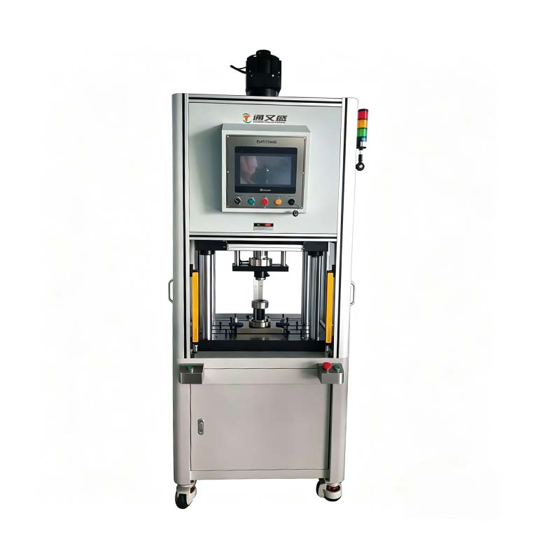
Four Column C Frame Servo Press Machine
Press-fit assembly is one of the principal applications for a servo press. Components such as bearings, bushings, shafts, pins, connectors, sleeves, and other interference-fit parts must often be installed with carefully controlled force and insertion depth. If the force is too high, the part or housing may be damaged. If the force is too low, the assembly may not reach the required position or retention strength.
The machine can control the approach movement, identify the contact point, and apply a programmed pressing profile. Force and displacement data can be evaluated during the cycle to determine whether the assembly is within the approved process window. This supports first-pass quality and reduces the risk of sending incorrectly assembled products to later operations.
According to the supplied application information, more than 200 press-fit assembly projects have been supported, with a stated first-pass yield of 99.2 percent. Actual results depend on the component design, tolerance stack-up, tooling, sensor calibration, and process parameters, but the experience demonstrates the machine’s suitability for repeatable precision assembly.
The servo press can also be used for punching applications involving holes, slots, or local forming features. Programmable motion allows the press to approach the material quickly and control the working portion of the stroke more carefully. This can help reduce unnecessary impact and improve consistency across repeated cycles.
Tool design remains essential in punching. The punch, die, clearance, material condition, lubrication, and alignment all influence the final result. The press provides the controlled force and motion platform needed to operate the tooling consistently. Application information indicates experience with more than 150 punching applications and hole diameter tolerance control within approximately ±0.05 mm under suitable process conditions.
Riveting requires a controlled deformation process. The rivet must be formed sufficiently to achieve the required joint strength without cracking the material, damaging nearby components, or creating excessive deformation. A servo press can follow a controlled displacement and force curve, allowing the forming operation to be adjusted according to rivet material and joint design.
Compared with a basic impact riveting method, a servo-controlled process can provide improved visibility into the relationship between forming force and final displacement. This is useful for detecting missing parts, incorrect rivet length, material variation, and incomplete forming. The supplied project information reports more than 200 riveting projects and a riveting strength compliance rate above 98 percent.
Powder compacting requires stable pressure application and consistent movement. The pressing process can influence density distribution, part geometry, surface quality, and the ability of the compacted component to withstand subsequent handling. A servo press can be programmed to approach the powder compacting tool smoothly and apply a controlled force profile.
Pressure-maintaining capability is particularly valuable in powder-forming applications. Once the target force has been achieved, the machine can hold the load for a specified period before returning. The supplied technical data lists a maximum pressure-maintaining time of 3,000 seconds for the available models. The required time in production will depend on the powder formulation, tooling, part size, and process specifications.
Application information describes more than 300 powder compacting cases and forming accuracy of approximately ±0.02 mm in selected applications. Final accuracy should always be verified through process trials and measurement of the finished components.
Sealing operations often require precise compression of gaskets, covers, rings, membranes, or other sealing components. Too little compression can cause leakage, while too much compression may damage the seal or distort the housing. A servo press can control the final position, applied force, and pressure dwell time to support repeatable sealing performance.
The machine can be configured to stop at a defined displacement, reach a force target, or evaluate both conditions. Where the application requires it, the control system can identify abnormal force-displacement behavior that may indicate a missing gasket, incorrect part orientation, damaged seal, or dimensional variation.
The supplied application record includes more than 500 sealing solutions and a reported leakage rate as low as 0.1 percent in suitable applications. The actual leakage performance depends on seal design, surface condition, material selection, cleanliness, tooling, and test method.
Springs must often be evaluated at one or more defined positions. The corresponding force can then be compared with a target range. A servo press provides controlled motion for compressing or extending a spring while measuring the relationship between position and force.
This capability can support incoming inspection, production testing, sorting, and final quality verification. It may be used for compression springs, elastic components, contact springs, and other parts that require a repeatable mechanical load test. Because the press can control travel and speed, it can help reduce variation caused by inconsistent manual testing.
Electronic components and small electromechanical assemblies often require low-impact, accurately positioned pressing. Connectors, terminals, housings, contacts, shields, and small inserts can be sensitive to excessive force or misalignment. The open working area facilitates fixture design, while the servo drive supports a controlled approach and precise final position.
For these applications, the ability to monitor process data can be as important as the pressing force itself. A production system can use force and displacement limits to identify an incorrectly loaded part before it moves to the next station. This helps protect expensive assemblies and supports higher process consistency.
The product family covers maximum pressure ratings from 1 kN to 300 kN. This allows the equipment to be selected according to the required working load rather than forcing every application into one general-purpose machine. Smaller models can be used for delicate component insertion and electronic assembly, while larger models can support more demanding forming and compacting operations.
Pressure settings can be adjusted in 1 N increments according to the supplied technical data. The minimum detection value is listed as 0.2 percent of the maximum pressure value. These figures indicate a control system intended for fine adjustment and process monitoring, although the effective accuracy in a real installation also depends on sensor class, calibration, mechanical friction, tooling design, temperature, and installation conditions.
Maximum stroke values vary by model. The listed stroke range begins at 200 mm for the smaller models and extends to 500 mm for larger units. This gives users flexibility when selecting between compact tooling arrangements and applications requiring deeper travel. Stroke should be selected together with the fixture height, component dimensions, tooling length, safety clearance, and required working position.
Press-fit speeds are listed up to 35 mm/s for several models, with lower maximum speeds for higher-capacity models. Fast-forward and return speeds can reach up to 100 mm/s on many models, while larger-capacity units have lower listed speeds. This arrangement allows the press to move quickly through non-working sections of the cycle and slow down during the controlled pressing stage.
Speed settings can be adjusted in 0.01 mm/s increments according to the provided specifications. Fine speed adjustment is useful for controlling contact behavior, reducing impact, adapting to fragile components, and optimizing cycle time. The correct speed profile should be established through application testing rather than selected only for the highest possible throughput.
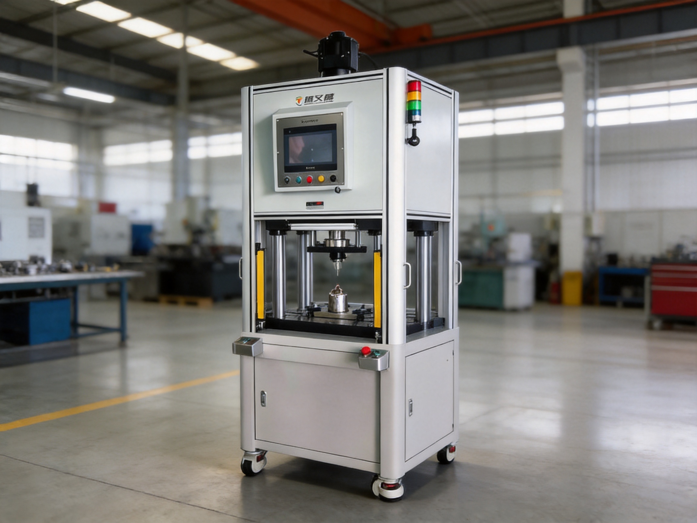
The following table summarizes the principal model data provided for the servo press family. The information should be confirmed against the final configuration, because dimensions, tooling arrangements, safety equipment, electrical options, and control functions may vary according to the customer’s application.
| Item | Unit | TYSP-01 | TYSP-05 | TYSP-10 | TYSP-20 | TYSP-30 | TYSP-50 | TYSP-70 | TYSP-100 | TYSP-150 | TYSP-200 | TYSP-250 | TYSP-300 |
|---|---|---|---|---|---|---|---|---|---|---|---|---|---|
| Maximum pressure | kN | 1 | 5 | 10 | 20 | 30 | 50 | 70 | 100 | 150 | 200 | 250 | 300 |
| Allowed pressure band | kN | 0.1–1 | 0.5–5 | 1–10 | 2–20 | 3–30 | 5–50 | 7–70 | 10–100 | 15–150 | 20–200 | 25–250 | 30–300 |
| Maximum stroke | mm | 200 | 200 | 200 | 200 | 250 | 350 | 350 | 500 | 500 | 500 | 500 | 500 |
| Maximum press-fit speed | mm/s | 35 | 35 | 35 | 35 | 35 | 35 | 35 | 35 | 30 | 25 | 20 | 15 |
| Fast-forward/return speed | mm/s | 100 | 100 | 100 | 100 | 100 | 100 | 100 | 100 | 50 | 50 | 30 | 30 |
| Speed setting unit | mm/s | 0.01 | 0.01 | 0.01 | 0.01 | 0.01 | 0.01 | 0.01 | 0.01 | 0.01 | 0.01 | 0.01 | 0.01 |
| Maximum pressure-maintaining time | s | 3000 | 3000 | 3000 | 3000 | 3000 | 3000 | 3000 | 3000 | 3000 | 3000 | 3000 | 3000 |
The TYSP model series includes several structural sizes. The supplied dimensional information lists lead, diameter, stroke, and overall dimensions for selected models. For example, the TYSP-05 and TYSP-10 models are listed with a 200 mm lead, 108 mm diameter, 285 mm stroke-related dimension, and 900 mm height for the working structure. Larger models use larger diameter and structural dimensions to accommodate higher loads and longer working ranges.
Machine selection should not be based on pressure capacity alone. The user should also evaluate the required stroke, working envelope, tooling height, daylight, table dimensions, component access, cycle time, and installation area. A model with excessive capacity may occupy more space and consume more energy than necessary, while an undersized model may operate near its mechanical limits and provide insufficient rigidity.
The first step is to determine the maximum process force, including an appropriate engineering margin. The second step is to define the force-displacement curve or final position required for the product. The third step is to check the physical dimensions of the tooling and workpiece. Finally, the user should review the desired production rhythm, automation interface, safety requirements, and data collection needs.
For high-volume production, the optimum model may be the one that provides the required force at the fastest stable cycle rather than the machine with the highest nominal capacity. For laboratory testing or flexible small-batch production, a model with a wide programmable range and generous stroke may be more useful than a specialized high-speed configuration.
The servo press includes an HMI panel for setting and monitoring process parameters. A clear HMI helps operators select a product recipe, adjust the pressing profile, monitor current force and position, and review cycle status. It can also provide alarm information and support troubleshooting when a cycle falls outside the permitted limits.
Typical parameters may include approach speed, pressing speed, return speed, target force, force limit, target position, position tolerance, pressure-holding time, and cycle completion conditions. Depending on the configured control architecture, the system may also support multi-stage pressing, which can include fast approach, slow contact, controlled pressing, dwell, and return.
Force-displacement monitoring is a central advantage of the servo press. Instead of confirming only that the motor moved or that a pressure threshold was reached, the system can evaluate how the force developed throughout the stroke. An abnormal curve may reveal a missing component, incorrect orientation, excessive friction, interference, a damaged part, or a tooling problem.
Process records can support continuous improvement and quality analysis. For example, engineers can compare force-displacement curves from accepted and rejected parts, identify trends in tool wear, and determine whether a component supplier’s dimensional variation is affecting the assembly. Data handling depends on the selected software and communication configuration, so the required interfaces should be defined before ordering.
Accurate stop-position control is important for insertion, forming, and sealing. A part may need to stop at a specific height, depth, or compression value. The servo system can be programmed to stop at the required position and to verify whether the achieved position is within tolerance.
Position control is also valuable when the final force is not sufficient by itself to define quality. Two parts could reach the same force at different positions because of dimensional variation or incorrect assembly. Monitoring both values creates a more complete evaluation of the process.
Some processes require the force to be applied gradually or maintained for a defined period. Controlled loading time can help prevent sudden impact, allow materials to settle, or ensure that adhesive, seal, or powder-forming conditions are maintained long enough to achieve the desired result.
The pressure-maintaining function supports dwell periods up to the listed maximum of 3,000 seconds. The actual production setting may be much shorter, but the broad range makes the press suitable for processes ranging from rapid assembly to extended compression or testing.
In other applications, the pressing cycle should stop when a specified force is reached. This is useful for contact assembly, spring testing, controlled interference fits, and material forming. The system can be configured with a target value and an upper safety limit so that the machine does not continue applying force after the acceptable condition has been achieved.
Mechanical presses are often effective for high-volume operations with fixed tooling and repetitive strokes. However, their motion profile is commonly determined by the crank, cam, or linkage design. Changing the pressing behavior may require mechanical modifications or different tooling.
A servo press provides greater flexibility because the motion is defined electronically. The user can adjust speed, position, dwell, and force-related conditions through the control system. This is beneficial when the same machine must process several product variants or when the production team wants to optimize the process without redesigning the drive mechanism.
Servo control can also reduce the need for full-force impact at the beginning of the working stroke. The machine can approach rapidly and then transition to a controlled pressing speed. This supports lower mechanical shock, improved operator comfort, and more consistent treatment of sensitive components.
Hydraulic presses can generate high force and are widely used for forming and assembly. However, hydraulic systems require pumps, valves, hoses, seals, and fluid management. Leakage control, oil temperature, filtration, and maintenance can influence the total operating cost and cleanliness of the production area.
An electric servo press uses an electromechanical drive architecture, reducing dependence on hydraulic fluid and associated components. It can provide clean operation, direct programmable motion, and efficient energy use during variable-duty cycles. For applications within the machine’s pressure range, this can simplify maintenance and improve process controllability.
Hydraulic technology remains appropriate for certain very-high-force applications and particular forming profiles. The selection should therefore be based on the actual process requirements. The advantage of the servo press is strongest where precise position control, data monitoring, variable recipes, clean operation, and responsive motion are priorities.
Pneumatic presses can be economical for simple pressing operations, but air compressibility may make fine force and position control more difficult. Air pressure fluctuations, cylinder friction, and changes in load can influence repeatability. Pneumatic systems may also consume compressed air continuously or require additional equipment for pressure regulation.
The servo press provides direct electronic control of movement and can apply a programmed force-displacement profile. It is therefore more suitable for applications where quality depends on measured position, controlled force, or a narrow process window rather than a simple binary pressing action.
The machine is produced by a high-technology manufacturer that integrates research and development, production, and sales. The company’s capabilities include electric cylinders, linear motion modules, linear motor modules, servo presses, robotic seventh axes, and multi-degree-of-freedom motion platforms. This product background is relevant because servo press performance depends not only on the frame but also on motion control, drive integration, mechanical transmission, sensing, and software.
An experienced research and development team supports the design process from concept development through engineering validation. Advanced design software can be used to evaluate mechanical structures, motion relationships, component interfaces, and installation requirements before production. This reduces the risk of dimensional conflicts and helps engineers develop equipment around the customer’s actual process rather than adapting the process to a generic machine.
High-precision CNC machining centers support the production of structural and motion-related parts. Precision machining is important for column alignment, mounting surfaces, guide interfaces, transmission components, tooling connections, and sensor installation points. Consistent machining quality contributes to smoother movement and better repeatability during pressing.
The company also maintains a portfolio of core patents and has developed algorithmic control software and multi-degree-of-freedom platform linkage systems. This indicates experience in both mechanical engineering and control engineering. For a servo press, the combination is important: a precise control algorithm cannot compensate fully for an unstable frame, and a rigid frame cannot deliver its potential without appropriate motion and sensing control.
Manufacturing quality is supported by an integrated approach that includes product design, component selection, machining, assembly, measurement, testing, and application validation. The supplied product description identifies the servo press as equipment that is assembled and measured as a complete system. This approach helps engineers evaluate the relationship between actual force and displacement rather than checking mechanical components only in isolation.
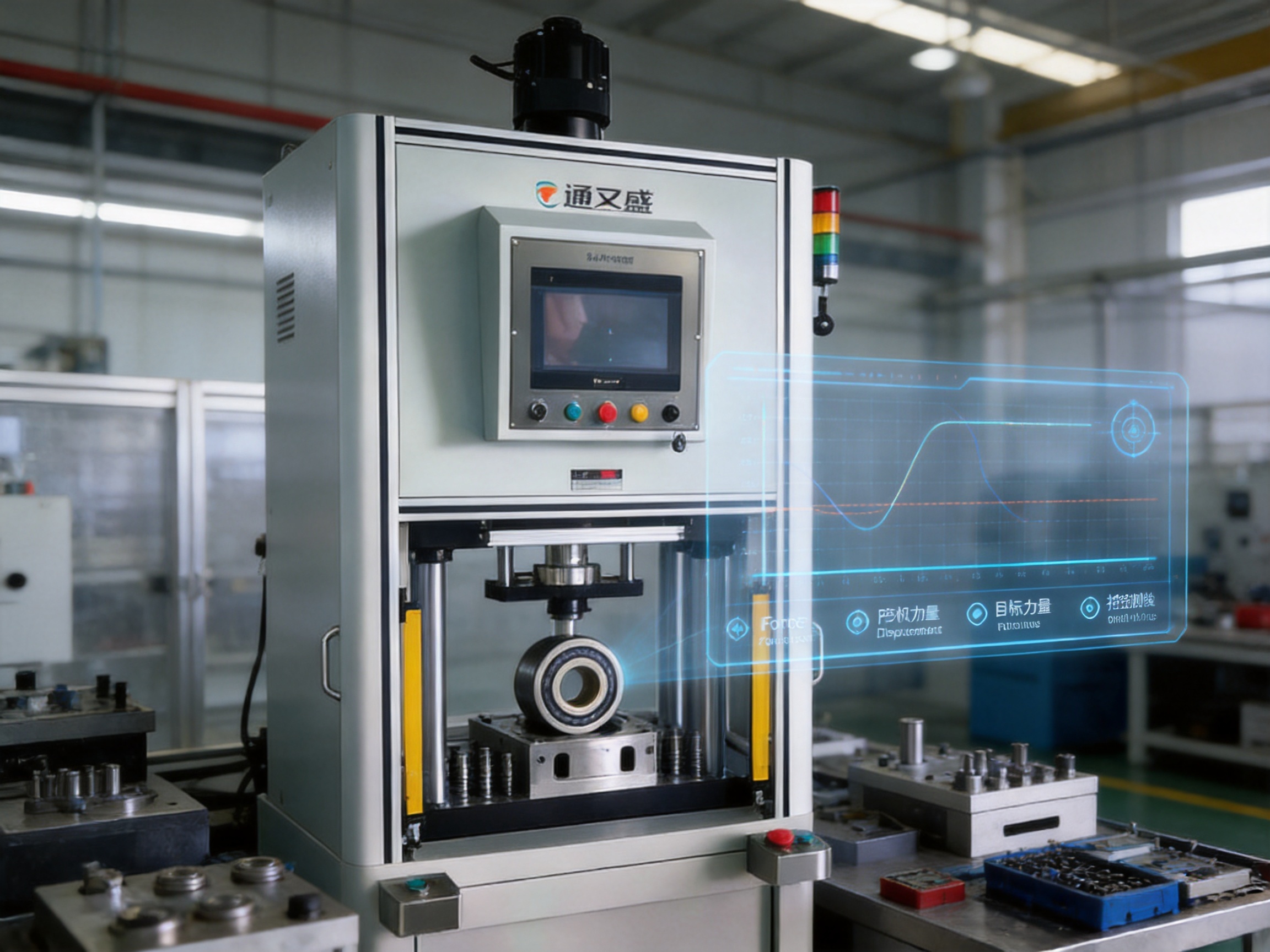
For precision pressing, quality control should cover both machine performance and application performance. Machine-level checks may include force sensor verification, position measurement, travel accuracy, speed stability, repeatability, frame alignment, emergency stop operation, and HMI functionality. Application-level checks may include the final insertion depth, joint strength, sealing performance, compact density, spring load, or hole tolerance.
The machine’s force-displacement relationship can be used as a process signature. Engineers can establish an acceptable window by running verified samples and recording the expected curve. Production cycles that exceed the upper or lower limits can then be flagged for inspection. This method supports preventive quality control rather than relying only on final inspection.
Tooling validation is equally important. The press cannot compensate for an incorrectly designed punch, die, fixture, guide, or support surface. Tooling should be aligned with the machine axis and designed to transmit force evenly. Workpieces should be supported in a way that prevents bending, tilting, or unintended movement during the cycle.
Calibration should be performed at appropriate intervals using traceable reference equipment. The required calibration schedule depends on operating conditions, cycle frequency, accuracy requirements, and internal quality standards. Regular inspection of columns, fasteners, guides, transmission components, sensors, cables, and tooling can help maintain stable operation.
The open C-frame arrangement makes the press suitable for integration with feeding, transfer, inspection, and unloading systems. A robot or linear motion module can place a part into the fixture, wait for the press-ready signal, and remove the completed assembly after the cycle is approved. Sensors can confirm part presence and fixture position before pressing begins.
The manufacturer’s experience with linear motion modules, electric cylinders, robotic seventh axes, and motion platforms can support the development of coordinated automation solutions. A press station may be combined with an electric cylinder for auxiliary clamping, a linear module for part transfer, or a robotic axis for extended movement along a production line.
Automation integration should include clear signal exchange between the press and external equipment. Typical signals may include machine ready, cycle start, cycle complete, pass, fail, alarm, fixture locked, part present, and emergency stop. Communication protocols and electrical interfaces should be defined during the project engineering stage.
For high-volume lines, automatic recipe selection and traceability can reduce operator error. Product identification may be linked to the correct force and position limits. The station can then record the result of every cycle, including the selected recipe, measured peak force, final position, dwell time, and pass or fail status.
The machine should be installed on a stable foundation capable of supporting the equipment and resisting the reaction forces generated during pressing. The installation area should provide sufficient clearance for loading, unloading, maintenance, electrical access, and safety guarding. Floor flatness, ambient temperature, humidity, dust, vibration, and power supply should be considered during planning.
Before production begins, the machine should be tested with the intended fixture and representative workpieces. Operators should verify that the tool is centered, the force direction is correct, the workpiece is fully supported, and the selected recipe is suitable. Trial runs should include normal parts, tolerance-limit parts, and controlled fault conditions where practical.
Routine operation should include inspection of the work area, tooling, cables, sensors, fasteners, and safety devices. Any unusual noise, vibration, force curve, travel behavior, or alarm should be investigated before continued production. A clean working area is especially important for electronic assembly, sealing, and precision component processing.
Because the machine uses an electric servo drive, maintenance is generally focused on mechanical inspection, sensor verification, electrical connections, software backups, and lubrication of applicable moving components. Maintenance intervals should follow the machine manual and be adjusted according to the actual production environment and cycle rate.
Operators should be trained in recipe selection, manual jog operation, tooling changeover, alarm handling, emergency procedures, and quality response. Access to the pressing area must be controlled through suitable guards, interlocks, two-hand controls, light curtains, or other safety measures appropriate to the machine layout and local regulations.
Energy efficiency is increasingly important because manufacturers are evaluating not only purchase price but also total operating cost. A servo press can reduce unnecessary energy use by controlling motor output according to the actual motion profile. During periods when the machine is not pressing or moving, the system can avoid the continuous power demand associated with some traditional drive arrangements.
Lower noise and the absence of hydraulic oil can also reduce indirect operating costs. A cleaner working environment may be beneficial for electronic and precision assembly. Maintenance planning can be simplified when fewer fluid-related components require inspection, replacement, and disposal.
The total value of the machine also includes yield improvement. If force and position monitoring prevents defective assemblies from moving downstream, the saving may exceed the energy reduction alone. Avoiding damage to expensive electronic components, housings, bearings, or sealing surfaces can significantly improve the economics of a controlled press process.
Cycle optimization is another source of value. The machine can use fast-forward movement when the press is away from the workpiece and switch to a controlled speed only during the working section. This helps balance throughput and process quality. The optimum profile should be determined through measured trials rather than by using maximum speed throughout the cycle.
Document the required force, stroke, final position, speed, dwell time, cycle time, and quality criteria. Identify whether the process is force-controlled, position-controlled, or dependent on both variables.
Record the part dimensions, material, tolerance, sensitivity to impact, required support points, and acceptable deformation. Determine whether the part must be inserted, formed, compacted, tested, riveted, punched, or sealed.
Choose a model with sufficient maximum pressure and stroke while retaining a reasonable operating margin. Avoid selecting a machine that will operate continuously at its maximum rating unless the application has been specifically engineered and validated for that condition.
Define the upper tool, lower fixture, guide system, sensors, ejectors, clamps, and changeover method. Ensure that the tooling can withstand the maximum load and that the workpiece is supported throughout the cycle.
Determine whether the application needs recipe management, force-displacement curve evaluation, pass/fail judgment, external communication, barcode identification, production data storage, or remote diagnostics. These requirements should be included in the initial quotation and engineering review.
Conduct sample trials using actual components and production tooling. Measure the final product characteristics and compare the results with the machine data. Establish process limits, inspection standards, maintenance procedures, and operator instructions before mass production.
Intelligent manufacturing depends on equipment that can sense, decide, act, and communicate. The Four Column C Frame Servo Press Machine supports these functions through force and displacement monitoring, programmable motion, HMI operation, recipe-based control, and compatibility with automated handling.
Its value is not limited to pressing force. The machine can become a controlled process station within a larger production system. It can verify whether the workpiece was loaded correctly, apply the programmed operation, evaluate the result, and provide a pass or fail signal. When production data is retained, engineers can use it to analyze trends and improve upstream or downstream processes.
The company’s broader experience in motion control, electric cylinders, linear modules, linear motors, robotic axes, and multi-degree-of-freedom platforms provides a foundation for customized automation. This is useful when the customer needs more than a standard standalone press and wants a complete workstation or integrated production line.
Established in 2013, the manufacturer has continued to expand its product development and manufacturing capabilities. Its cooperation with state-owned enterprises, defense technology institutions, and universities has supported the integration of industry, academia, and research. This background contributes to an engineering-oriented approach focused on reliability, innovation, and practical industrial application.
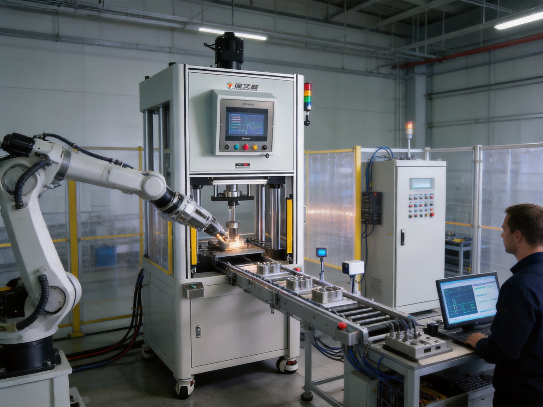
It is a servo-driven pressing machine that combines a rigid four-column support structure with an open C-frame working area. It is designed to control pressing force, position, speed, and pressure-maintaining time for applications such as assembly, riveting, punching, sealing, compacting, and testing.
The supplied model family covers maximum pressure ratings from 1 kN to 300 kN. The correct model should be selected according to the required process force, stroke, tooling size, cycle time, and structural requirements.
The machine can process small mechanical parts, bearings, bushings, shafts, pins, electronic components, seals, riveted assemblies, powder-formed parts, springs, and other components that require controlled pressing or testing.
Yes. The machine is designed to monitor and control the relationship between force and displacement. Users can configure force targets, position targets, speed profiles, stop conditions, and pressure-holding periods according to the application.
The supplied technical specifications list a maximum pressure-maintaining time of 3,000 seconds for the model range. The appropriate production dwell time depends on the material, tooling, product design, and process requirements.
Yes. The open C-frame area supports access for robots, transfer units, feeders, and other automation equipment. Electrical signals, communication interfaces, fixture sensors, recipe management, and pass/fail outputs should be specified during project planning.
Servo control provides more precise electronic control of position, speed, and force. It is better suited to applications where the pressing process must be measured and repeated within a defined force-displacement window. Pneumatic presses may remain suitable for simple operations that do not require the same level of control.
The open front area makes loading, unloading, visual inspection, fixture access, and automation integration more convenient. It is particularly useful for compact parts and applications involving frequent product changeovers.
The machine is an electrically driven servo press, so it is not based on a conventional hydraulic power system. This can reduce hydraulic fluid management and support a cleaner production environment. Final maintenance requirements depend on the selected configuration.
Maintenance should include inspection of tooling, guide and transmission components, sensors, cables, fasteners, electrical connections, safety devices, and applicable lubrication points. Calibration and preventive maintenance should follow the machine manual and the production environment.
Servo presses can be configured with different pressure capacities, stroke lengths, tooling arrangements, fixtures, sensors, software functions, and automation interfaces. Customization should be determined through an engineering review of the product and production process.
Useful information includes the workpiece drawings, material, required force, stroke, target position, cycle time, process curve, tooling details, production quantity, automation requirements, safety standards, data requirements, and installation conditions. Sample parts are also valuable for process trials.
The Four Column C Frame Servo Press Machine provides a balanced solution for manufacturers that need structural rigidity, open access, programmable motion, and measurable process control. Its pressure range from 1 kN to 300 kN, stroke options up to 500 mm, adjustable speed profiles, fine setting resolution, and pressure-maintaining capability support a wide variety of industrial applications.
Its advantages over conventional mechanical, hydraulic, and pneumatic equipment are most evident in applications that require controlled force and position, low process variation, recipe flexibility, data monitoring, clean operation, and automation compatibility. Press-fit assembly, punching, riveting, powder compacting, sealing, spring testing, and electronic component processing can all benefit from a controlled servo-driven process.
The product is supported by a manufacturer with experience in electric cylinders, linear motion systems, servo equipment, robotic axes, and multi-degree-of-freedom platforms. Advanced design software, high-precision CNC machining, application engineering, complete-system measurement, and research cooperation contribute to the development of reliable automation equipment for intelligent manufacturing.
For the best result, the machine should be selected through a complete application review rather than by pressure rating alone. When force, displacement, tooling, process data, safety, and automation requirements are considered together, the servo press can serve as a high-value production platform for accurate assembly, forming, testing, and quality assurance.
1. Product specification data for the Four Column C Frame Servo Press Machine, including model range, pressure, stroke, speed, dimensions, and pressure-maintaining parameters.
2. Application summary for press-fit assembly, punching, riveting, powder compacting, sealing, and spring testing.
3. Technical information regarding servo press HMI operation, force-displacement monitoring, controlled loading, stop position, and stop force.
4. General engineering principles for servo motion control, electromechanical pressing, force measurement, and industrial automation integration.
5. Manufacturing capability information covering research and development, CNC machining, automation equipment production, control software, and motion system engineering.
6. General guidelines for machine installation, tooling validation, calibration, preventive maintenance, operator training, and industrial machine safety.
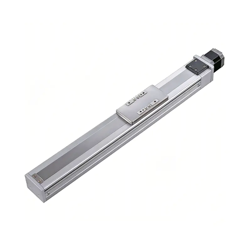 0.01mm High Precision Ball Screw Driven Rail-Embedded Linear Module
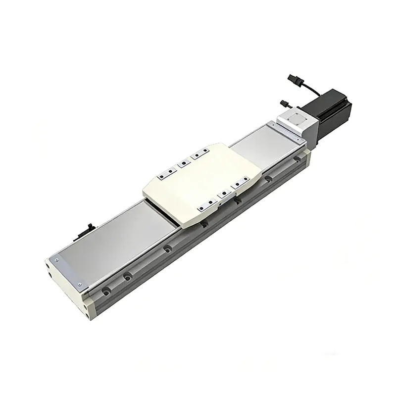 Heavy Load Ball Screw Driven Rail-Embedded Linear Module
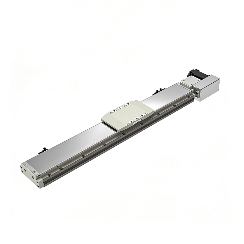 110KG Load Long Stroke Rail-Embedded Linear Module
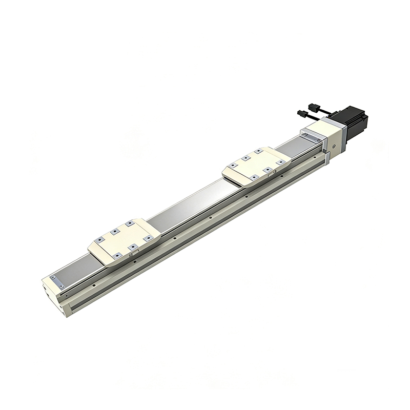 Dual-Slider High Precision Rail-Embedded Linear Module
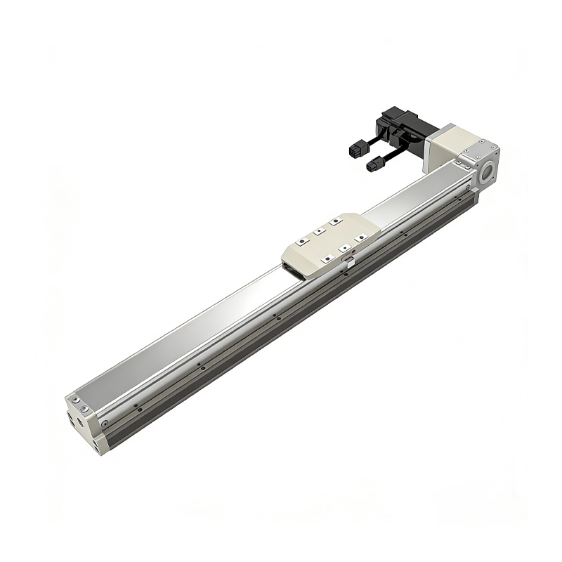 Belt Driven Dust-Proof Rail-Embedded Linear Module
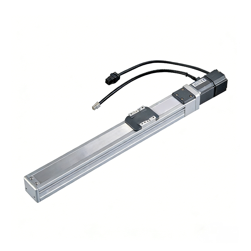 0.01mm High Precision Light Load Ball Screw Linear Module
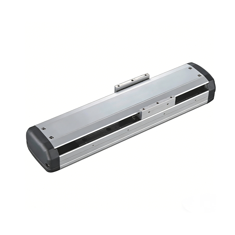 Ball Screw Linear Module with Built-in Sensor
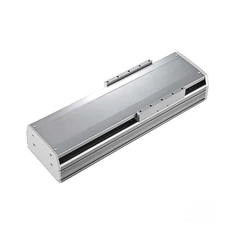 2000mm Long Stroke Ball Screw Linear Module
This 2000mm Long Stroke Ball Screw Linear Module is customized for large-range linear movement automation tasks, support...
READ MOREThis 2000mm Long Stroke Ball Screw Linear Module is customized for large-range linear movement automation tasks, support...
READ MOREThis 2000mm Long Stroke Ball Screw Linear Module is customized for large-range linear movement automation tasks, support...
READ MOREThis 2000mm Long Stroke Ball Screw Linear Module is customized for large-range linear movement automation tasks, support...
READ MORE
If you are interested in our products, please leave us a message. We look forward to providing you with
professional services!
Innovation and transcendence make factory intelligent manufacturing efficient and convenient!
+86 186 2508 0683
19962977901
sales@sz-tys.com
Building 5, Suzhou Mudu International Science and Technology Innovation Park, Jinfeng South Road, Suzhou City, Jiangsu Province, China
