


 English
 Français
 русский
 عربى
عربى Español
 Deutsch
Tel
+86 186 2508 0683

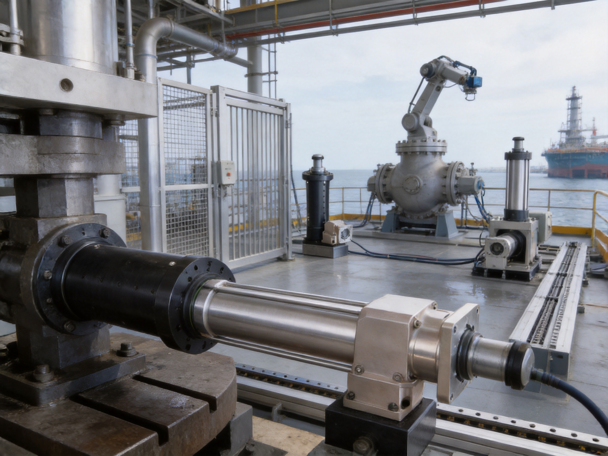
Industrial automation increasingly requires motion systems that combine high force, accurate positioning, fast response, straightforward installation, and dependable operation in difficult environments. In sectors such as petrochemical processing, offshore engineering, pharmaceutical production, chemical manufacturing, food processing, and heavy industrial equipment, a conventional actuator may not provide the required combination of corrosion resistance, safety, controllability, and service life.
The stainless steel explosion-proof electric cylinder is designed for these demanding applications. It integrates a robust electric drive system, a precision screw transmission, a corrosion-resistant structural design, and safety-focused protection measures into one compact linear actuator. The result is a motion solution capable of producing stable thrust and controlled reciprocating movement without the complex hydraulic infrastructure associated with traditional hydraulic cylinders.
Based on the TYSC250 configuration, this electric cylinder offers a rated load of up to 300 kilonewtons, a screw stroke range from 0 to 3,000 millimeters, multiple reduction ratios, several motor power options, and a rated speed of 250. It also provides selectable functions such as anti-rotation, limit switches, and multiple mounting and load-connection arrangements. These features allow the actuator to be adapted to various machine layouts and operating requirements.
Its stainless steel construction is particularly valuable where humidity, heavy dust, salt spray, chemical exposure, or frequent cleaning may shorten the life of standard painted-steel actuators. Its explosion-proof design is intended to reduce the risk of electrical ignition in hazardous working environments. The actuator also has an IP65 protection rating, helping protect internal components against dust ingress and water projected from certain directions.
This article examines the structure, operating principles, technical specifications, manufacturing strengths, application advantages, installation considerations, maintenance requirements, and selection criteria of the stainless steel explosion-proof electric cylinder.
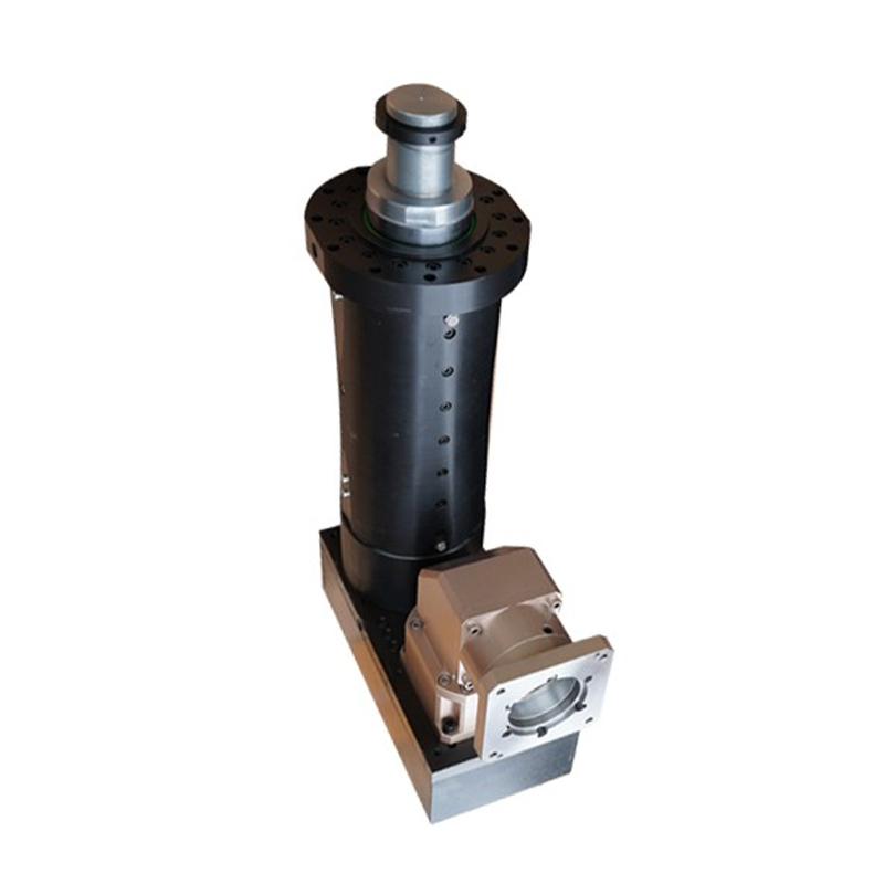
Stainless Steel Explosion-proof Electric Cylinder
A stainless steel explosion-proof electric cylinder is an electrically powered linear actuator designed to convert rotary motor motion into controlled linear movement. The motor drives a screw mechanism through a direct connection and reduction arrangement. As the screw rotates, the nut or transmission element moves axially, causing the actuator rod to extend or retract.
Unlike a pneumatic cylinder, the actuator does not require compressed air. Unlike a hydraulic cylinder, it does not require an oil pump, reservoir, valve block, or network of hydraulic pipes. Instead, the linear movement is generated through an integrated electromechanical transmission system that can be controlled by a motor drive, servo system, or compatible automation controller.
The stainless steel body and core components are selected to improve resistance to corrosion and wear. This is useful in locations where water, condensation, salt, chemical vapor, dust, or cleaning agents are present. The material choice also supports applications that require a durable and hygienic external surface.
The explosion-proof design focuses on controlling potential ignition sources. Electrical connections, motor protection, sealing, grounding, mechanical construction, and operating conditions must all be considered when an actuator is installed in a hazardous area. The specific certification and allowable application zone should always be confirmed against the final product configuration and local regulations before installation.
In practical terms, the electric cylinder provides four important functions: it generates linear force, controls position, regulates motion speed, and transmits movement to an external mechanism. It can be used for pressing, pushing, pulling, clamping, lifting, positioning, forming, opening, closing, and synchronized machine movement.
The use of stainless steel for the cylinder body and important internal components provides a strong advantage over conventional carbon-steel actuators with basic surface coatings. Painted or plated surfaces may eventually be damaged by impact, abrasion, moisture, or chemical exposure. Once the protective layer is compromised, corrosion can spread beneath the coating and affect structural integrity.
Stainless steel provides a more durable material foundation for applications involving humidity, washdown, salt-laden air, and corrosive atmospheres. It is especially valuable in offshore installations, chemical plants, pharmaceutical workshops, and industrial production areas where equipment may be exposed to aggressive substances or regular cleaning procedures.
Corrosion resistance can also help reduce unplanned maintenance. A component that retains its surface integrity for a longer period is less likely to experience seizing, thread deterioration, increased friction, or mechanical contamination caused by rust particles. This can contribute to more stable motion performance and a longer usable service period.
In flammable and explosive environments, the choice of an actuator cannot be based only on thrust and stroke. The equipment must also be evaluated for its potential to generate an ignition source. Electrical sparks, excessive surface temperature, damaged wiring, static electricity, and mechanical faults may all create safety concerns if the equipment is not suitable for the area.
The explosion-proof electric cylinder is designed with safety-focused construction intended to help prevent electrical ignition during normal operation. Its application value is therefore greater than that of an ordinary electric actuator when the surrounding atmosphere may contain flammable gas, vapor, mist, or combustible dust.
However, the phrase “explosion-proof” should not be treated as a substitute for a complete hazardous-area assessment. Users should verify certification markings, temperature class, gas or dust group, wiring method, enclosure requirements, grounding arrangements, and installation limitations for the exact model. A properly selected actuator must be integrated into a complete explosion-protection system.
The TYSC250 configuration provides a rated force of 300 kilonewtons. This high load capability allows the actuator to address applications that exceed the practical capacity of many compact electric actuators. It can be considered for heavy-duty pressing, forming, lifting, closing, adjustment, positioning, and mechanical loading operations.
High thrust is useful when a machine must overcome substantial resistance or maintain force during a process. Examples include industrial presses, heavy gates, valve mechanisms, forming tools, material handling equipment, structural adjustment systems, and production fixtures.
A high-force actuator must always be matched with suitable guides, frame structures, bearings, couplings, and load paths. The actuator should not be used as the sole guide for an offset or side load unless the product design specifically allows it. Proper machine integration protects the screw, rod, bearings, and housing from excessive bending moments.
The available screw stroke range is 0 to 3,000 millimeters. This broad range gives machine designers flexibility when specifying extension length and working travel. A shorter stroke may be selected for compact pressing or positioning systems, while a longer stroke can support lifting, opening, sliding, or transfer mechanisms.
Stroke selection affects the actuator’s stability, speed, buckling resistance, installation length, and load capacity. The maximum possible stroke should not automatically be selected for every application. A practical design uses only the travel required by the machine while allowing sufficient clearance for assembly, maintenance, and safety limits.
Because the actuator is driven electrically, its speed and position can be coordinated with sensors, controllers, and production sequences. The rated speed is listed as 250, while actual linear speed depends on the motor, reduction ratio, screw lead, controller settings, load, duty cycle, and operating conditions.
Electrical control allows the cylinder to be integrated into automatic cycles. The system can be configured for controlled acceleration, deceleration, positioning, dwell time, and return movement. This is an important advantage compared with basic hydraulic or pneumatic systems that may require additional valves and pressure-control components to achieve similar motion behavior.
Fast response is particularly useful in production lines where cycle time, synchronization, and repeatable timing directly affect output. It also supports applications requiring coordinated movement between several actuators or between the actuator and other machine axes.
The stated repeatability is plus or minus 0.02. Repeatability is important in applications where a tool, workpiece, mold, fixture, or mechanism must return to a consistent position during repeated cycles.
Actual system accuracy depends on more than the actuator itself. Factors include screw manufacturing quality, backlash, bearing preload, motor encoder resolution, control algorithm, structural deformation, temperature variation, external load, mounting rigidity, and the quality of the feedback system. Even so, a precision electric cylinder provides a strong foundation for repeatable automated motion.
A hydraulic system typically requires a pump, tank, hoses, pressure valves, filters, fittings, and regular fluid maintenance. A pneumatic system requires a compressor, air treatment equipment, valves, tubing, and pressure regulation. By contrast, an electric cylinder can be installed as a more self-contained motion unit.
Reducing the number of auxiliary components can simplify machine design and help decrease the potential failure points. It may also reduce installation time, floor-space requirements, noise, fluid leakage risks, and routine maintenance work. Electrical control further allows operating data and fault signals to be incorporated into a factory automation system.
The following table summarizes the principal information provided for the TYSC250 electric cylinder. Final specifications should be confirmed against the selected motor, reduction ratio, mounting configuration, safety certification, and customer-specific design.
| Specification | Value or Option |
|---|---|
| Model | TYSC250 |
| Product type | Stainless steel explosion-proof electric cylinder |
| Motor connection | Direct connection |
| Screw diameter | 100 millimeters |
| Screw lead | 20 millimeters |
| Screw stroke | 0 to 3,000 millimeters |
| Rated force | 300 kilonewtons |
| Reduction ratio | 1:4, 1:5, 1:10, 1:20, or 1:50 |
| Motor power | 3, 4, 5.5, 7.5, or 11 kilowatts |
| Rated speed | 250 |
| Anti-rotation | Available as a selectable option |
| Limit switch | Available as a selectable option |
| Repeatability | Plus or minus 0.02 |
| Protection rating | IP65 |
| Load connection | External thread, internal thread, rod-end bearing, double pin holes, or customized arrangement |
| Mounting options | Bottom threaded hole, base plate, front flange, tail flange, tail projection pin, tail pin hole, or customized arrangement |
The direct motor connection contributes to a compact power-transmission layout. Depending on the selected configuration, the reduction ratio can be used to balance speed and thrust. A lower reduction ratio may support faster movement, while a higher reduction ratio can provide greater mechanical advantage and better control for heavy loads.
The 100-millimeter screw diameter offers a substantial mechanical transmission platform for heavy-duty applications. The 20-millimeter screw lead establishes the relationship between screw rotation and linear travel. When the screw lead, motor speed, and reduction ratio are considered together, the designer can select a practical combination of force, speed, and duty cycle.
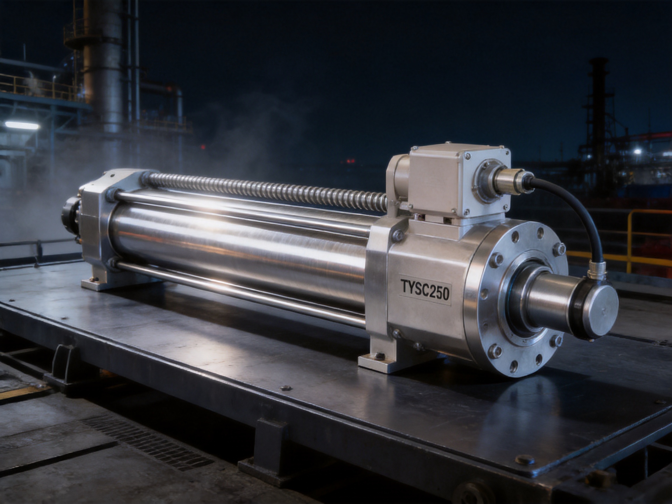
The motor supplies rotary power to the actuator. Through the direct connection and selected reduction arrangement, motor rotation is transferred to the screw mechanism. The reduction ratio influences the rotational speed reaching the screw and the torque available at the transmission element.
For applications requiring high thrust, a greater reduction ratio can help increase available mechanical force while lowering output speed. For applications where rapid travel is more important, a lower reduction ratio may be appropriate, provided that the load, duty cycle, and thermal conditions remain within permissible limits.
Motor selection should consider continuous force, peak force, acceleration, deceleration, duty cycle, environmental temperature, control method, and required safety functions. A motor with a higher nominal power rating is not automatically the best choice. The ideal selection provides sufficient capacity without excessive energy consumption or unnecessary mechanical stress.
The screw converts rotary motion into linear movement. As the screw rotates, the mating transmission element travels along the screw axis. This mechanism provides a controlled and repeatable means of extending and retracting the rod.
The screw is one of the most important load-bearing components in the cylinder. Its diameter, lead, material, heat treatment, surface condition, lubrication, bearing support, and manufacturing accuracy affect the actuator’s service life and motion quality. Precision machining and careful inspection are therefore essential parts of the production process.
An anti-rotation function can help prevent the actuator rod or connected load from rotating during extension and retraction. This is useful when the external tool, fixture, or workpiece must maintain a fixed orientation.
The anti-rotation option should be selected according to the load geometry and the expected external forces. It should not be used to compensate for excessive side loading. If the mechanism creates significant lateral force or bending torque, separate linear guides or support structures should be provided.
Limit switches can define the safe end positions of the actuator. They may be used to stop motion before the mechanical end of travel, provide position signals to a controller, or support automatic sequencing.
Limit-switch placement and adjustment should be verified during commissioning. The control system should include appropriate emergency-stop and overload protection, and operators should not rely on a limit switch as the only protection against a dangerous machine movement.
The performance of a high-force explosion-proof electric cylinder depends heavily on the quality of its engineering and manufacturing process. A reliable product is not created by assembling a motor, screw, and tube without comprehensive design control. The actuator must be engineered as a complete system in which materials, tolerances, sealing, thermal behavior, electrical protection, and mechanical load paths work together.
The manufacturer’s development approach covers electric cylinders, linear motion modules, linear motor modules, servo presses, robotic seventh axes, and multi-degree-of-freedom motion platforms. This broader product background supports the design of actuators that can be integrated into complete automation systems rather than treated as isolated components.
Experience across multiple motion technologies helps engineers compare electric, servo, screw-driven, and coordinated multi-axis solutions. It also supports the development of practical interfaces, mounting arrangements, control requirements, and customized mechanical configurations.
Advanced design software can be used to develop three-dimensional models, check component interfaces, evaluate assembly clearances, and analyze the relationship between force, stroke, speed, and installation geometry. Digital modeling helps identify potential interference before physical production begins.
Design verification should consider axial force, buckling, bearing loads, screw stress, housing rigidity, thermal expansion, sealing, vibration, and service access. In hazardous environments, the design process must also consider cable entries, grounding, enclosure integrity, surface temperature, and compatibility with the intended area classification.
High-precision CNC machining centers support the manufacture of housings, flanges, screw-related components, bearing seats, mounting interfaces, and customized connection parts. Controlled machining improves dimensional consistency and helps maintain alignment between the motor, transmission, screw, and output rod.
Accurate bearing seats and coaxial mounting surfaces are particularly important. Misalignment may increase friction, produce uneven wear, generate noise, reduce repeatability, and shorten the life of the screw and bearings. Precision machining therefore contributes directly to smooth operation and long-term reliability.
Stainless steel components must be selected, machined, cleaned, and assembled appropriately for the intended environment. Material traceability, surface quality, weld or joint quality where applicable, and protection against contamination all influence corrosion performance.
In addition to the main structural material, engineers must evaluate seals, fasteners, bearings, lubricants, cable glands, connectors, and other supporting components. A stainless steel housing alone does not guarantee complete corrosion resistance if incompatible auxiliary materials are used.
During assembly, the screw, bearings, reduction mechanism, rod, and housing must be positioned with suitable alignment and preload. Correct assembly reduces unwanted play and supports stable force transmission.
Critical assembly operations may include bearing installation, screw alignment, sealing installation, lubrication, fastening, electrical connection, and end-position adjustment. Controlled procedures help ensure that each actuator meets the intended mechanical and safety requirements.
Quality inspection should cover dimensional accuracy, surface condition, movement smoothness, load performance, electrical integrity, sealing, limit-switch operation, and repeatability. Testing may be conducted under no-load and loaded conditions, depending on the product configuration and application requirements.
A practical inspection program can include visual examination, dimensional measurement, insulation and grounding checks, operational cycling, noise and vibration observation, stroke verification, and load testing. For explosion-proof configurations, documentation and certification checks are also essential.
The company’s investment in research and development, advanced manufacturing equipment, engineering personnel, and patented technologies supports a structured product-development process. Such capabilities are important when customers require customized stroke lengths, mounting interfaces, load connections, control arrangements, or integration with existing automation equipment.
Hydraulic cylinders are widely used for high-force applications, but their supporting systems can be large and complex. Pumps, tanks, hoses, valves, filters, and fluid-cooling equipment may be required. Hydraulic leakage can create environmental, housekeeping, and maintenance concerns, particularly in clean production areas or offshore locations.
The electric cylinder offers a more integrated alternative. It can provide programmable motion, easier feedback integration, and a cleaner installation without a hydraulic oil circuit. It can also reduce the amount of auxiliary equipment around the machine.
Hydraulic technology may still be appropriate for applications requiring extremely high continuous force, very high shock tolerance, or specific fail-safe behavior. The correct choice depends on the process. However, where controllable positioning, reduced infrastructure, and cleaner operation are priorities, the electric cylinder can provide meaningful advantages.
Pneumatic cylinders are simple and economical for basic two-position movement, but compressed air is inherently compressible. This can make precise positioning and stable force control more difficult. Air preparation, leakage, compressor capacity, and noise may also affect operating costs.
An electric cylinder can provide more precise motion control and better integration with servo systems. It can be programmed for multiple positions, adjustable speed, controlled acceleration, and coordinated movement. It is therefore better suited to processes requiring repeatable positioning rather than simple extension and retraction.
Standard electric actuators may provide good positioning performance but lack the material durability, sealing, or safety construction needed for harsh or hazardous environments. A stainless steel explosion-proof model is designed to address environmental and safety conditions that ordinary automation actuators may not withstand.
The difference is especially important in applications involving salt spray, chemical vapor, dust, humidity, or potentially flammable atmospheres. Selecting a standard actuator for such a location may create premature corrosion, electrical faults, or unacceptable safety risks.
Some imported motion systems offer sophisticated functions but may involve long lead times, complex communication channels, expensive replacement parts, and limited customization. A manufacturer with its own engineering and production resources can often respond more directly to custom requirements.
Customization may include mounting plates, rod-end connections, stroke length, anti-rotation arrangements, limit-switch positions, motor power, reduction ratio, and control interfaces. Direct technical communication can simplify application evaluation and reduce the risk of selecting an unsuitable configuration.
Petrochemical plants, chemical-processing facilities, storage terminals, and related installations may contain flammable gases, vapors, or combustible dust. Actuators may be required for valves, dampers, process equipment, safety barriers, mechanical handling systems, and positioning devices.
In these environments, corrosion resistance and explosion-protection requirements must be evaluated together. The actuator should be selected according to the area classification, process chemicals, temperature range, mounting location, and required movement profile.
Offshore platforms expose equipment to salt spray, high humidity, wind-driven moisture, vibration, and difficult maintenance conditions. Stainless steel construction can provide valuable resistance to the marine atmosphere, while the electric drive can simplify installation compared with a distributed hydraulic system.
Applications may include equipment positioning, hatch or gate operation, lifting mechanisms, adjustment systems, process control, and heavy-duty mechanical handling. The final installation should account for marine-grade fasteners, cable protection, drainage, grounding, and inspection accessibility.
Pharmaceutical manufacturing often requires cleanable equipment, controlled processes, and reliable repeatability. The stainless steel surface can be advantageous where washdown and sanitation are necessary. Electric control supports accurately sequenced operations, controlled dosing mechanisms, positioning systems, pressing, and packaging equipment.
Hygienic design requirements vary by process. Users should evaluate surface finish, crevices, lubricant compatibility, cleaning chemicals, sealing materials, and the need for special validation documentation.
The 300-kilonewton rated force makes this type of actuator suitable for selected pressing and forming operations. It can be used to apply controlled linear force to a tool, fixture, mold, or workpiece.
Press applications require careful calculation of force, stroke, speed, impact energy, cycle frequency, heat generation, and structural stiffness. The actuator should be supported by an adequately designed frame, and the control system should include suitable overload and emergency-stop functions.
Electric cylinders can operate lifting arms, pushers, transfer devices, positioning tables, gates, loading mechanisms, and adjustable supports. The programmable motion profile can help reduce impact and improve coordination with conveyors, robots, sensors, and vision systems.
The actuator can serve as a linear axis in robotic equipment, special-purpose machinery, simulation devices, and industrial automation systems. Its selectable mounting arrangements allow designers to adapt the cylinder to different frame architectures.
When used as part of a multi-axis system, the actuator should be evaluated for synchronization, dynamic load, cable routing, emergency behavior, and control-system compatibility. The manufacturer’s experience with linear modules and multi-degree-of-freedom platforms can support more complex integration projects.
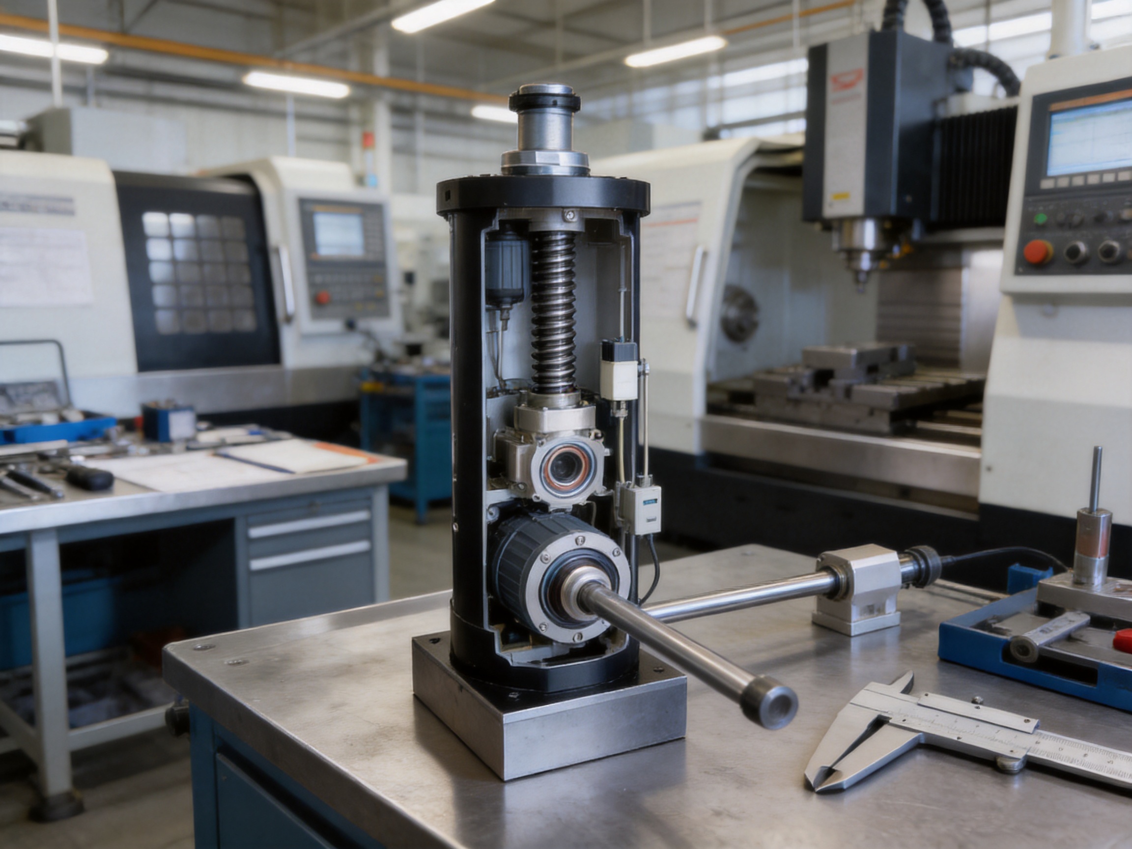
The available mounting arrangements include a bottom threaded hole, base plate, front flange, tail flange, tail projection pin, and tail pin hole. These options support fixed, hinged, and customized installation structures.
A flange-mounted arrangement may be suitable when the actuator must be aligned with a machine frame or tooling plate. A pin-based arrangement can allow angular movement around a joint. The correct selection depends on whether the actuator body or rear assembly must remain fixed while the rod follows a pivoting mechanism.
The listed load-connection choices include an external thread, internal thread, rod-end bearing, double pin holes at the rod end, and customized solutions. The connection should match the geometry, movement, and force direction of the driven mechanism.
Where the load changes angle during movement, a rod-end bearing or pin connection may be preferable to a rigid threaded connection. Where the load remains precisely aligned, a threaded connection may provide a compact and rigid interface. Any connection must be secured against loosening and must be rated for the expected axial and side forces.
The actuator should be aligned with the direction of force. Side loads, bending moments, and excessive eccentricity can damage the screw, bearings, rod, or housing. External guide rails, linear bearings, or parallel support structures should be used when the load is not naturally self-guided.
Alignment should be checked throughout the complete stroke rather than only at the retracted position. Misalignment may become more severe as the rod extends, especially in long-stroke applications.
Wiring must comply with the requirements for the intended hazardous area and local electrical regulations. Cable glands, connectors, grounding, shielding, isolation, overload protection, and emergency-stop circuits must be selected as part of the complete system.
Users should not modify explosion-protection features without authorization. Drilling, machining, replacing cable entries, changing covers, or using non-approved accessories may affect the safety integrity of the equipment.
Preventive maintenance helps preserve motion accuracy, sealing performance, and mechanical life. Maintenance frequency should be established according to operating hours, load, speed, environment, temperature, contamination, and duty cycle.
Operators should regularly inspect the actuator for corrosion, unusual noise, vibration, overheating, loose fasteners, damaged cables, seal deterioration, and changes in movement smoothness. Any increase in backlash, reduced repeatability, or abnormal power consumption should be investigated before a major failure occurs.
The screw and related transmission components should receive the lubrication specified for the exact product configuration. Using an incompatible lubricant may damage seals, reduce corrosion resistance, or affect friction and temperature behavior.
Limit switches and anti-rotation components should be checked during scheduled inspections. Mounting bolts, rod-end connections, and frame interfaces should be inspected for loosening or deformation. In hazardous areas, inspection procedures must comply with site safety rules and permit-to-work requirements.
Cleaning should be performed using methods and chemicals compatible with the stainless steel, seals, cable components, and protective surfaces. High-pressure water should not be directed at areas that are not designed for such exposure, even when the actuator has an IP65 rating.
The first selection parameter is the required axial force. Designers should distinguish between continuous force, peak force, starting force, holding force, and emergency or shock loads. The actuator’s rated force should not be exceeded, and suitable safety factors should be applied according to the application.
The second parameter is stroke. The required travel should include the actual machine movement plus suitable allowances for end clearances, installation tolerances, and maintenance access. Excessive unused stroke may increase the installation length and reduce stability.
The third parameter is operating speed. The designer should define average speed, maximum speed, acceleration, deceleration, cycle time, and dwell periods. These values should then be matched with the motor power, reduction ratio, screw lead, and thermal capacity.
The fourth parameter is duty cycle. A cylinder operating continuously at high force and speed has different requirements from one operating for a few short cycles per hour. Duty-cycle calculations should include acceleration energy, holding time, pauses, environmental temperature, and cooling conditions.
The fifth parameter is environmental suitability. Users should identify humidity, dust, chemicals, salt spray, washdown, temperature, vibration, and hazardous-area classification. The stainless steel and IP65 design may be highly suitable for many harsh environments, but the complete product configuration must still be verified for the site.
The sixth parameter is installation geometry. Mounting style, rod-end connection, available space, retracted length, extended length, cable routing, access for service, and external guides should all be defined before ordering.
The seventh parameter is control compatibility. The motor, drive, encoder, limit switches, feedback, communication system, and safety circuit must work together. A complete technical review can prevent problems caused by incompatible voltage, control signals, connector arrangements, or feedback requirements.
A major advantage of working with an experienced automation manufacturer is the ability to evaluate the entire motion requirement rather than simply select a catalog number. The manufacturer can review force, stroke, speed, mounting, load connection, environment, and control requirements together.
Customization may involve a special base plate, non-standard flange, modified pin-hole arrangement, alternative rod-end connection, different stroke, selected reduction ratio, motor power, anti-rotation design, limit-switch configuration, or integration with a larger motion platform.
The company’s history of developing electric cylinders, linear motion modules, servo presses, robotic axes, simulation platforms, and multi-degree-of-freedom systems provides a broad engineering base for such projects. Its research and development activities, CNC machining resources, design software, and accumulated patents support the creation of application-specific products.
For international customers, technical communication should include drawings, load diagrams, duty-cycle information, installation conditions, control requirements, and safety documentation. Clear information at the design stage improves quotation accuracy, manufacturing efficiency, and commissioning results.
The main benefit is improved resistance to corrosion, wear, humidity, dust, salt spray, and certain aggressive working conditions. Stainless steel can help preserve structural integrity and reduce maintenance compared with ordinary painted-steel construction, although the suitability of the exact material must be checked against the process chemicals.
It is designed for applications with high explosion-protection requirements, but the exact certification, area classification, gas or dust group, temperature class, and installation conditions must be verified before use. The actuator should be installed as part of a complete hazardous-area safety system.
The listed rated force is 300 kilonewtons. Actual allowable force depends on operating speed, stroke, duty cycle, load direction, installation method, temperature, and the selected motor and reduction configuration.
The listed screw stroke range is 0 to 3,000 millimeters. The final usable stroke should be selected according to the machine’s movement, stability, installation space, and safety requirements.
Yes. Its high rated force and controllable linear motion make it suitable for selected pressing and forming applications. The machine frame, tooling, guides, control system, overload protection, and emergency-stop functions must be designed for the pressing process.
No. It is an electrically driven actuator and does not require a hydraulic pump, oil tank, hydraulic valve block, or hydraulic pipeline network. It does require a suitable motor-control and electrical safety system.
IP65 indicates protection against dust ingress and protection against water projected by a nozzle from certain directions under defined test conditions. It does not mean that the actuator can be submerged or exposed to every type of high-pressure washdown.
The listed options are 1:4, 1:5, 1:10, 1:20, and 1:50. The appropriate ratio depends on the required force, speed, motor characteristics, duty cycle, and control requirements.
Yes. Anti-rotation is listed as a selectable option. External guides may still be necessary when the driven mechanism produces side loads or bending moments.
Yes. Limit switches are listed as a selectable option and can be used to define end positions or provide signals to the control system. They should be integrated with suitable safety and control circuits.
Options include a bottom threaded hole, base plate, front flange, tail flange, tail projection pin, tail pin hole, and customized arrangements. The correct choice depends on the machine frame and the required degree of pivoting or fixed alignment.
The listed choices include an external thread, internal thread, rod-end bearing, double pin holes at the rod end, and customized solutions. The connection should be selected according to load direction, joint movement, alignment, and maintenance requirements.
Correct sizing, accurate alignment, suitable external guides, proper lubrication, regular inspection, clean installation, appropriate electrical protection, and operation within the rated load and duty cycle can all improve service life.
Customization is available for several mounting and load-connection arrangements. Customers should provide load, stroke, speed, duty cycle, environmental, control, and installation information so the engineering team can confirm the appropriate configuration.
The stainless steel explosion-proof electric cylinder is a heavy-duty linear motion solution for applications that demand force, precision, environmental durability, and enhanced safety. Its stainless steel construction supports operation in humid, dusty, corrosive, and marine environments. Its explosion-proof design addresses the need for safer actuation in locations where flammable atmospheres may be present, subject to confirmation of the final certification and site requirements.
The TYSC250 configuration combines a 300-kilonewton rated force, a 0-to-3,000-millimeter stroke range, a 100-millimeter screw diameter, a 20-millimeter screw lead, multiple reduction ratios, several motor-power choices, selectable anti-rotation and limit-switch functions, plus a range of mounting and load-connection options.
Compared with conventional hydraulic or pneumatic systems, the actuator can reduce auxiliary equipment, simplify installation, improve electronic control, and support programmable motion. Compared with ordinary electric actuators, its stainless steel and explosion-protection features make it more appropriate for harsh and safety-sensitive industrial environments.
Its final performance depends on correct sizing, accurate installation, suitable guides, proper controls, and compliance with the requirements of the working area. With careful engineering and professional manufacturing, the electric cylinder can become a reliable component in petrochemical equipment, offshore systems, pharmaceutical machinery, heavy presses, automated handling lines, robotics, and advanced industrial automation.
1. Product specification information for the TYSC250 stainless steel explosion-proof electric cylinder.
2. General principles of industrial electric actuator design, screw transmission, and linear motion control.
3. General guidance for enclosure protection classifications and IP65 environmental protection.
4. General engineering practices for hazardous-area electrical equipment selection and installation.
5. General design principles for machine guarding, emergency stops, overload protection, and industrial automation safety.
6. General maintenance practices for screw-driven actuators, bearings, seals, and linear motion systems.
7. General principles of stainless steel material selection for humid, corrosive, marine, pharmaceutical, and chemical-processing environments.
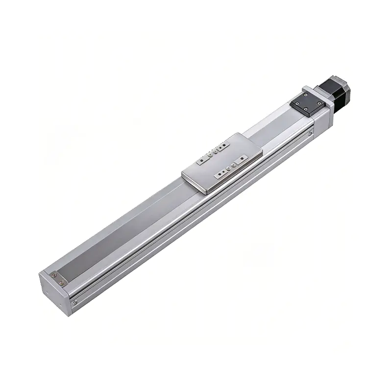 0.01mm High Precision Ball Screw Driven Rail-Embedded Linear Module
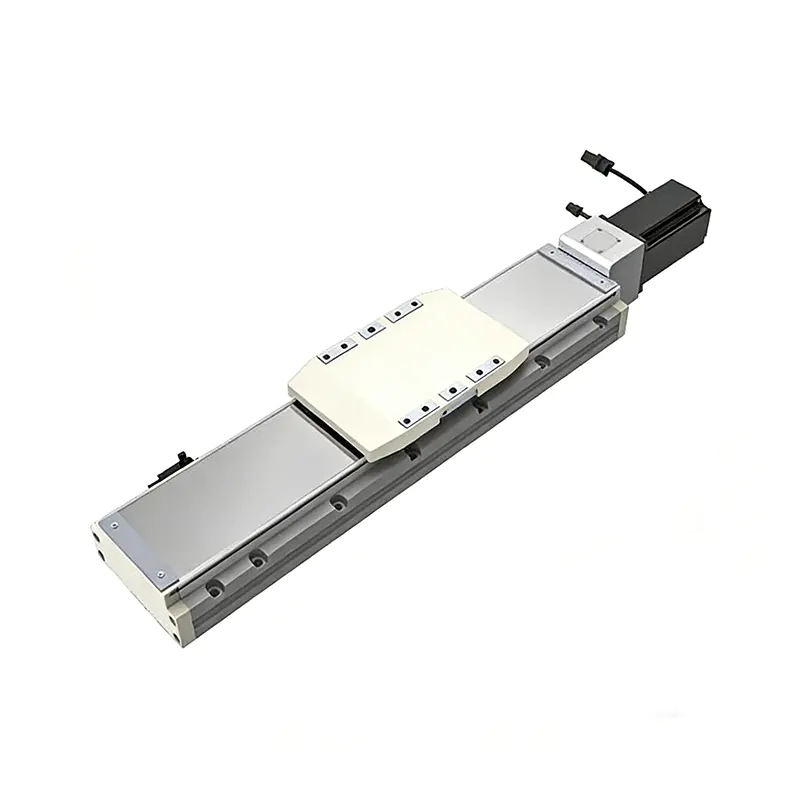 Heavy Load Ball Screw Driven Rail-Embedded Linear Module
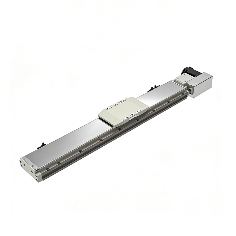 110KG Load Long Stroke Rail-Embedded Linear Module
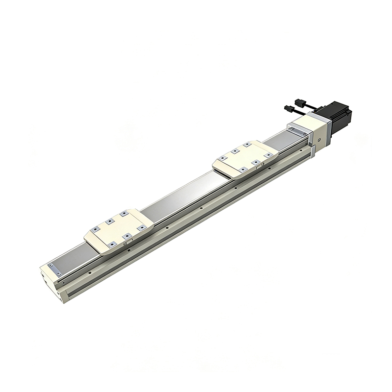 Dual-Slider High Precision Rail-Embedded Linear Module
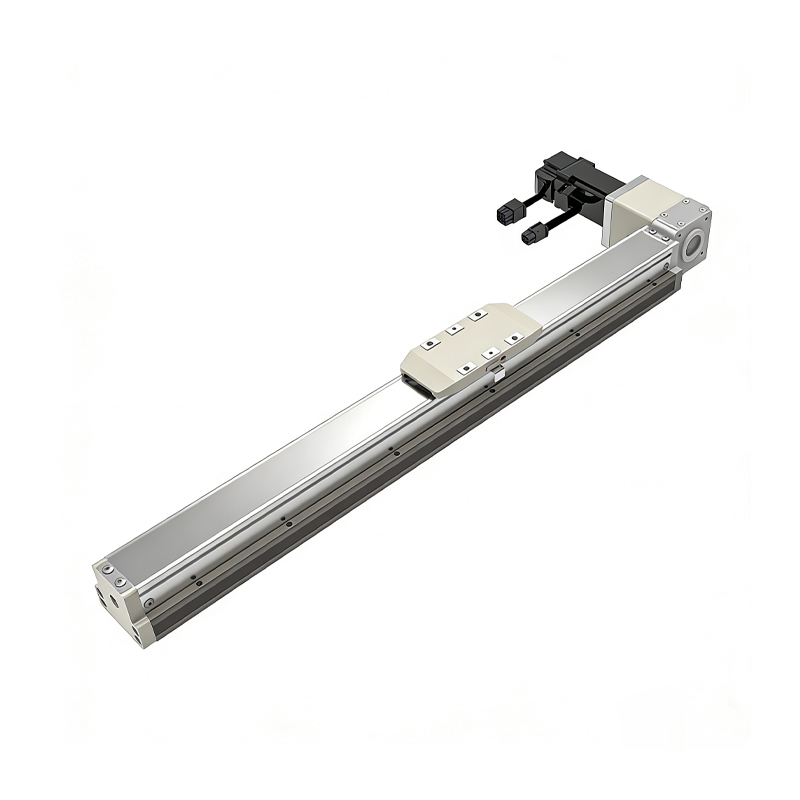 Belt Driven Dust-Proof Rail-Embedded Linear Module
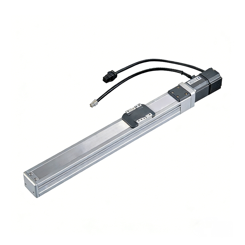 0.01mm High Precision Light Load Ball Screw Linear Module
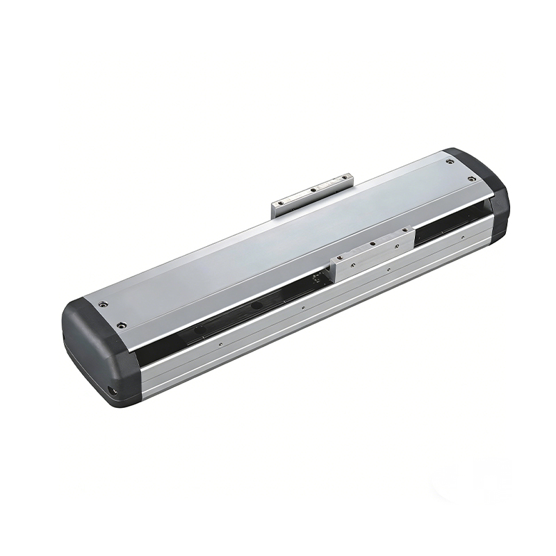 Ball Screw Linear Module with Built-in Sensor
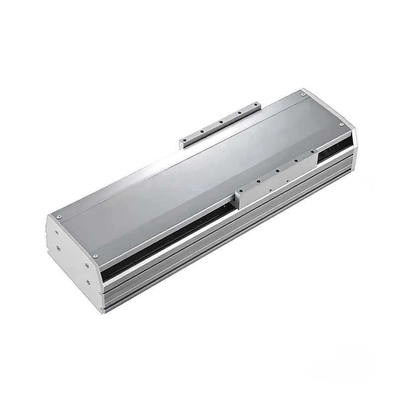 2000mm Long Stroke Ball Screw Linear Module
This 2000mm Long Stroke Ball Screw Linear Module is customized for large-range linear movement automation tasks, support...
READ MOREThis 2000mm Long Stroke Ball Screw Linear Module is customized for large-range linear movement automation tasks, support...
READ MOREThis 2000mm Long Stroke Ball Screw Linear Module is customized for large-range linear movement automation tasks, support...
READ MOREThis 2000mm Long Stroke Ball Screw Linear Module is customized for large-range linear movement automation tasks, support...
READ MORE
If you are interested in our products, please leave us a message. We look forward to providing you with
professional services!
Innovation and transcendence make factory intelligent manufacturing efficient and convenient!
+86 186 2508 0683
19962977901
sales@sz-tys.com
Building 5, Suzhou Mudu International Science and Technology Innovation Park, Jinfeng South Road, Suzhou City, Jiangsu Province, China
